Setting up communication for a Schneider Electric Air Circuit Breaker (ACB) involves configuring various parameters to ensure proper integration with your monitoring and control systems. This guide will provide a detailed step-by-step process to configure communication settings for Schneider ACBs, particularly focusing on the Masterpact series, which is commonly used in industrial and commercial applications.
1. Introduction to Schneider ACB Communication
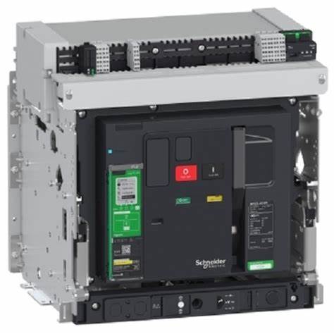
Schneider Electric’s Masterpact ACBs can be equipped with communication capabilities to integrate with building management systems (BMS), energy management systems (EMS), and other supervisory control and data acquisition (SCADA) systems. These capabilities allow for remote monitoring, control, and data logging.
2. Prerequisites
Hardware Requirements
- Schneider Electric Masterpact ACB with a communication module (e.g., Modbus, Ethernet)
- Communication cables (e.g., RS485 cables for Modbus)
- A computer with the necessary software installed (e.g., Schneider Electric’s EcoStruxure Power Commission)
Software Requirements
- EcoStruxure Power Commission or other relevant configuration software
- Drivers and firmware updates (if necessary)
3. Communication Protocols
Schneider ACBs support various communication protocols, including:
- Modbus RTU: A serial communication protocol used over RS485.
- Modbus TCP: A network protocol used over Ethernet.
- Ethernet/IP: Commonly used in industrial settings for networked communication.
- IEC 61850: A protocol for electrical substation automation.
4. Configuring Communication Settings
Step-by-Step Configuration for Modbus RTU
Step 1: Connect the Communication Module
- Connect the Modbus communication module to the ACB as per the manufacturer’s instructions.
- Ensure the RS485 cable is properly connected to the communication module and the monitoring system or network.
Step 2: Configure the Modbus Address
- Using the EcoStruxure Power Commission software or the front display panel of the ACB, navigate to the communication settings menu.
- Set the Modbus address (slave ID) for the ACB. This is a unique identifier for each device on the Modbus network. Commonly, addresses range from 1 to 247.
- Example: Set Modbus address to
1.
- Example: Set Modbus address to
Step 3: Set the Baud Rate
- Set the communication baud rate, which defines the speed of data transmission. Common baud rates are 9600, 19200, and 38400.
- Example: Set baud rate to
19200.
- Example: Set baud rate to
Step 4: Configure the Parity
- Choose the parity setting, which can be none (N), even (E), or odd (O).
- Example: Set parity to
Even.
- Example: Set parity to
Step 5: Set the Stop Bits
- Set the number of stop bits, usually 1 or 2.
- Example: Set stop bits to
1.
- Example: Set stop bits to
Step 6: Save and Apply Settings
- Save the settings and apply them. The ACB should now be ready to communicate over the Modbus RTU network.
Step-by-Step Configuration for Modbus TCP
Step 1: Connect the Ethernet Module
- Connect the Ethernet communication module to the ACB and the network switch or router using Ethernet cables.
Step 2: Configure the IP Address
- Access the communication settings menu via EcoStruxure Power Commission or the ACB’s front display.
- Set a static IP address for the ACB. Ensure it is within the same subnet as the network to which it is connected.
- Example: Set IP address to
192.168.1.10.
- Example: Set IP address to
Step 3: Set the Subnet Mask
- Configure the subnet mask to define the network segment.
- Example: Set subnet mask to
255.255.255.0.
- Example: Set subnet mask to
Step 4: Configure the Gateway Address
- If the ACB needs to communicate outside the local network, set the gateway address.
- Example: Set gateway to
192.168.1.1.
- Example: Set gateway to
Step 5: Save and Apply Settings
- Save the settings and apply them. The ACB should now be configured for communication over Modbus TCP.
5. Verifying Communication
Using EcoStruxure Power Commission
- Open EcoStruxure Power Commission on your computer.
- Add the ACB to your project by entering its communication parameters (e.g., IP address for Modbus TCP or Modbus address for Modbus RTU).
- Test the connection to ensure the ACB is communicating correctly. The software should be able to read data from the ACB and control it if necessary.
Network Analyzer Tools
- Use network analyzer tools (e.g., Wireshark for Ethernet-based protocols) to monitor the communication and troubleshoot any issues.
6. Advanced Configuration
Configuring Ethernet/IP
Step 1: Connect the Ethernet/IP Module
- Connect the Ethernet/IP communication module to the ACB and the network.
Step 2: Set IP Configuration
- Configure the IP settings as described for Modbus TCP (static IP, subnet mask, gateway).
Step 3: Configure the Assembly Instances
- Use the EcoStruxure Power Commission to configure the assembly instances for Ethernet/IP communication, defining input and output assemblies for the device.
Step 4: Configure RPI (Requested Packet Interval)
- Set the RPI, which determines how frequently data packets are sent over the network.
- Example: Set RPI to
100ms.
- Example: Set RPI to
Step 5: Save and Apply Settings
- Save and apply the settings to enable communication over Ethernet/IP.
7. Troubleshooting Common Issues
No Communication
- Check Connections: Ensure all physical connections are secure.
- Verify Settings: Double-check all communication settings (address, baud rate, parity, stop bits, IP configuration).
- Test with Known Good Device: Use a known good device to test the network and isolate the issue.
Intermittent Communication
- Check Network Load: High network traffic can cause intermittent communication issues.
- Check Cables: Faulty or damaged cables can cause intermittent issues.
- Update Firmware: Ensure the latest firmware is installed on the ACB.
Incorrect Data
- Verify Data Mapping: Ensure that the data registers are correctly mapped and configured.
- Check Protocol Compatibility: Ensure the monitoring system is compatible with the communication protocol and settings used by the ACB.
8. Documentation and Support
Manufacturer Documentation
- Refer to the Schneider Electric manuals and technical documentation for detailed instructions and specifications.
Technical Support
- Contact Schneider Electric’s technical support for assistance with complex issues or advanced configurations.
9. Best Practices
Regular Maintenance
- Perform regular maintenance and checks on communication settings to ensure continuous and reliable operation.
Backup Configuration
- Backup the configuration settings periodically to avoid loss of data and simplify recovery in case of system failure.
Training and Knowledge Sharing
- Train personnel on the communication settings and troubleshooting techniques to ensure they can handle issues effectively.
10. Conclusion
Configuring communication settings for Schneider Electric ACBs, such as the Masterpact series, is essential for integrating them into modern monitoring and control systems. By following the detailed steps outlined in this guide, you can ensure proper setup and reliable communication, enhancing the overall efficiency and safety of your electrical distribution system. Regular maintenance, adherence to best practices, and leveraging manufacturer support will further contribute to the successful operation of your ACB communication network.


![Voltage Sag vs Interruption: Causes, Impact, and Fixes A plant can lose a production line from a blink of power, even when the lights come back almost at once. If you've seen a VFD trip, a contactor drop out, or a PLC reset after a split-second dip, you've seen power quality turn into a production problem. The issue is often not a full outage. It's a short voltage event that sensitive equipment can't ride through. Start with the basics, and the failure starts to make sense. What voltage sag and interruption mean A voltage sag is a short drop in RMS voltage below normal, usually to 10% to 90% of rated voltage, for 0.5 cycles up to 1 minute. In a 415 V system, a brief drop to 280 V or 250 V is a sag, not a blackout. Duration matters. If voltage stays low for more than a minute, that is usually undervoltage, not sag. A sag arrives fast, recovers fast, and can still stop a machine. This quick comparison makes the difference easier to see: EventWhat happensTypical durationVoltage sagVoltage drops but does not go to zero0.5 cycles to 1 minuteVoltage interruptionVoltage is zero or near zeroLess than 1 minuteUndervoltageVoltage stays below normal for longerMore than 1 minute An interruption is more severe because supply is lost completely, or almost completely, for less than a minute. If it clears in a few seconds after auto-reclosing, it is a momentary interruption. If it stays off beyond a minute, it becomes a sustained interruption. Why these events happen The most common cause is a fault on the power system. That could be a single line-to-ground fault, line-to-line fault, double line-to-ground fault, or a three-phase fault. When fault current rises, voltage drops across the network until protection clears the problem. If the fault is on your feeder, you may see a sag first and then an interruption when the breaker opens. If the fault is on another feeder from the same substation, your breaker may never trip, but your plant can still see a bus voltage dip. That is why equipment can trip even when "our feeder never opened." Large motor starting is another frequent cause. An induction motor can draw five to seven times full-load current during start. In a weak system, or where the motor is large compared with the transformer, that inrush can create a temporary sag. Transformer energization, capacitor switching, welding loads, arc furnaces, and sudden heavy loading can do the same. Why a tiny dip can stop a large machine > The main motor may ride through a sag, but the control power often won't. Older plants had more electromechanical loads, and many of them tolerated short dips. Modern plants rely on PLCs, VFDs, servo drives, electronic power supplies, sensors, relays, and SCADA. Those devices make automation possible, but many are more sensitive to voltage dips than the motor they control. Massive steel control panels and heavy machinery dominate the floor as overhead lights cast a chaotic, flickering glow. Sharp shadows and sparks suggest a sudden surge in the facility power grid. [https://user-images.rightblogger.com/ai/f382171e-d1b1-4320-b7eb-289d9b53ee27/industrial-factory-power-instability-93e17dc7.jpg] A short sag may not stop a spinning motor because inertia keeps it moving. Still, the contactor coil can drop out, the VFD can detect undervoltage, and the PLC power supply can reset. Once the control chain breaks, the process stops. In process plants, that can mean lost batches, reset time, scrap, labor loss, and delayed delivery. Magnitude and duration both matter. Some equipment can tolerate 80% voltage for five cycles, but not 40% for the same time. That is why ride-through curves matter, and why event recording matters too. Good monitoring tools, such as monitoring power quality with PME 2024 R2 [https://www.interestingautomation.com/schneider-pme-2024-r2/], help capture minimum voltage, duration, and affected phases. Practical ways to reduce voltage sag problems The most cost-effective fix starts with the weak point. If a 200 kW machine trips because a 230 V PLC supply resets, you usually do not need to protect the whole machine. You need to protect the control power. * Specify ride-through performance when buying critical PLCs, drives, relays, and controls. * Add a small UPS, DC backup, or capacitor ride-through module for control power. * Use a voltage sag compensator or dynamic voltage restorer for sensitive process loads. * Apply online UPS systems where transfer time cannot be tolerated. * Consider motor-generator or flywheel systems where short interruptions happen often. * Use static transfer switches only when the two sources are truly independent. Source quality matters too. Utilities reduce events with better protection coordination, faster fault clearing, line maintenance, tree trimming, and feeder automation. On the plant side, grid automation and fault visibility also help, which is why tools for using Easergy T300 for fault detection [https://www.interestingautomation.com/brief-explain-easergy-t300-features-benefits-and-complete-guide/] are relevant in systems that need faster disturbance response. Final thoughts A blink in voltage can do more damage to production than a short outage, because the failure often happens inside the control system before anyone sees a breaker trip. That is the core lesson behind voltage sag and interruption studies. The best fix is rarely the biggest one. Find what actually trips, measure how deep and how long the event lasts, and protect the most sensitive part first. A brief dip should not turn into hours of downtime.](https://www.interestingautomation.com/wp-content/uploads/2026/05/Voltage-Sag-vs-Interruption-Causes-Impact-and-Fixes-150x150.jpg)


![Why MV Switchgear Fails: 5 Causes That Lead to Major Faults A 36 kV switchgear panel can sit closed for two years, carry load without complaint, and still fail on the one day you need it to clear a fault. That is the risk hiding behind a quiet panel. If the breaker won't trip, if protection doesn't detect the fault, or if insulation breaks down inside the cubicle, the result can be fire, arc flash, equipment loss, and a hard production stop. The real job is not waiting for failure and reacting later. It is spotting the warning signs before the panel runs out of margin. What counts as a switchgear failure Not every defect in a medium-voltage panel is a true failure. That distinction matters because reliability studies do not count every bad lamp, loose label, or minor nuisance the same way they count a breaker that won't trip. IEC 62271-1, clause 3.1.12, defines a major failure as a failure of switchgear and controlgear that causes the loss of one or more fundamental functions. It also says a major failure leads to an immediate change in system operating conditions, such as backup protection having to clear a fault, or forces unscheduled removal from service within 30 minutes. Major failures affect the core job of the panel In plain language, a major failure means the switchgear can no longer do one of its main jobs. Those jobs include switching, protection, monitoring, and control. If a fault occurs and the protection system does not detect it, that is a major failure. If the relay sends a trip command and the vacuum circuit breaker stays closed, that is also a major failure. The same goes for a situation where one bus section fails and the plant has to shift supply to another bus to keep running. The standard's wording about "immediate change in operating conditions" is useful because it points to real plant behavior, not theory. When primary protection fails and backup protection has to step in, the system has already moved into an abnormal state. If a breaker will not close because of a spring problem and must be removed from service at once, the equipment has lost its reliability. Minor failures are different, even if they still need attention A minor failure is anything that does not take away those core functions. An LED indication lamp that has gone dark is annoying, but it does not stop the panel from switching or protecting the system. A cosmetic defect may need correction, but it does not belong in the same category as a breaker mechanism that sticks. That distinction helps when you look at failure data. Most reliability studies focus on major failures, because those are the events that threaten safety, uptime, and equipment life. > A panel does not become dangerous only when it burns. It becomes dangerous the moment it can no longer switch, protect, or isolate a fault as intended. The five failure modes behind most serious problems Across published guidance and field experience, the same trouble spots keep showing up in MV switchgear. Insulation breakdown and mechanical faults sit near the top, while overheating, environmental stress, and aging keep chipping away at the system until something gives. A single medium voltage switchgear panel stands inside a clean and brightly lit industrial facility. [https://user-images.rightblogger.com/ai/f382171e-d1b1-4320-b7eb-289d9b53ee27/medium-voltage-switchgear-panel-dc9d5203.jpg] This quick summary helps frame where the risk usually sits: | Failure mode | Typical share or impact | Common triggers | Best early warning | | | | | | | Insulation failure | About 20% to 30% of failures | Partial discharge, insulation defects, contamination | PD testing or continuous PD monitoring | | Internal arc | Less about share, more about severity | Insulation breakdown, loose parts, human error, foreign objects | Arc detection plus proper panel design and rating | | Busbar and connection overheating | Major contributor within remaining failures | Poor joints, high contact resistance, loose terminations | Thermal inspection or continuous temperature monitoring | | Environmental and aging effects | Significant long-term driver | Moisture, dust, corrosion, seal failure, material degradation | Inspection, humidity monitoring, life assessment | | Mechanical failures | About 30% to 40% of failures | Trip coil issues, dry lubrication, worn parts, weak spring energy | Breaker monitoring and functional testing | The headline is simple. A switchgear failure usually starts as a small loss of margin, then turns into a major event when nobody is watching. Insulation failure usually starts where you can't see it Insulation failure is one of the biggest reasons MV switchgear fails. The hard part is that the panel can look healthy from the outside while the weakness grows inside cable insulation, busbar insulation, or instrument transformer resin. Partial discharge is small at first, then destructive Partial discharge starts when electrical stress concentrates inside tiny voids, impurities, or defects within insulation. In a cable, for example, a manufacturing void or a badly prepared termination can create a weak point. Stress collects there because the local dielectric strength is lower. Once the stress exceeds what that spot can withstand, a localized discharge starts. It is called "partial" because the discharge does not bridge the full insulation path at first. Still, the damage does not stay small. Repeated discharges eat away at the insulation until a much larger fault develops. A wood beam with termites offers a good comparison. The outside may still look sound, while the inside has already lost strength. By the time the damage is visible, the collapse is close. In MV panels, partial discharge often shows up in cable terminations, cable insulation itself, CT and VT epoxy insulation, and insulated busbar systems. The danger is that it rarely gives an obvious warning unless you are looking for it. For a broader research view, the review of medium-voltage switchgear fault detection [https://www.mdpi.com/1996-1073/15/18/6762] covers common detection methods and fault behavior in more detail. Periodic partial discharge testing helps, but it has a limit. You only see the panel at the moment of the test. Continuous monitoring fills the blind spot between maintenance visits. That difference matters more as the switchgear ages. Internal arc is where hidden weakness becomes immediate danger Internal arc is one of the worst events that can happen inside switchgear because it combines heat, pressure, smoke, and metal vapor in a confined space. It is not the same thing as a normal short circuit. An internal arc is a fault that develops inside the enclosure and puts people nearby at direct risk. Insulation failure can trigger it. So can a loose connection, a dropped tool, a foreign object left behind after maintenance, or simple human error. A screwdriver bridging two phases is enough to turn a routine task into a violent event. Besides fire damage, the smoke from an internal arc is hazardous on its own. That is why this topic is not only about asset protection. It is also about human safety. Modern panels may include arc detection systems that watch for both light and current. When they detect an arc, they send a trip command in milliseconds. It also pays to check whether the panel has been tested for internal arc classification, because that tells you how the equipment is expected to behave during this kind of fault. Heat at joints and contacts can undo a good panel Every electrical joint carries some risk. If the connection is poor, resistance rises. When current keeps flowing through that resistance, I squared R losses turn into heat, and heat becomes the start of the next failure. This issue appears again and again at busbar joints, cable terminations, breaker contacts, and earthing connections. The busbar connection between two panels is a common weak point. So is the cable end where termination quality depends on careful stripping, clean surfaces, correct materials, and proper tightening. In withdrawable breakers, primary contact engagement needs extra attention because poor seating can cause local hot spots. The physics is simple, but the effect is expensive. A small increase in contact resistance can push the temperature high enough to damage insulation, oxidize surfaces, weaken spring pressure, and set up the next arc fault. That is why overheating is a recurring theme in switchgear failure analysis, including this overview of switchgear failures and solutions [https://blog.exertherm.com/causes-of-switchgear-failures-and-solutions]. Good workmanship cuts most of this risk at the start. Joints need the right preparation, the right torque, and the right method from the manufacturer. After installation, thermal checks matter. A handheld IR inspection helps during rounds, but large sites with many panels often need more than occasional scans. Fixed thermal sensors on critical joints can track temperature all day and flag a problem before the panel forces a shutdown. Age and environment wear down the margin of safety Switchgear does not fail only because something was assembled badly. Time and environment also wear down the panel, even when operation looks normal. A typical service life is often described as about 25 to 30 years, though real life depends on duty, environment, maintenance, and design. Once equipment gets deep into that age range, the risk rises. Insulation can crack. Corrosion can creep across sheet metal and hardware. Seals can weaken in gas-filled compartments. Contacts wear. Springs lose strength. Materials that looked stable for years start to drift out of their original condition. Environmental stress speeds that process up. Moisture is a common problem because it lowers insulation resistance and can help contamination become conductive. Dust does the same thing when it settles where it should not. Some reported failure summaries tie a large share of busbar trouble to moisture and dust exposure, and this medium-voltage switchgear problem summary [https://www.green-energy-elec.com/common-problems-in-medium-voltage-switchgear/] highlights that pattern clearly. The fix depends on the site. Air-insulated panels in humid, dusty areas need more cleaning and inspection. Higher IP ratings help when the environment is harsh. In some applications, enclosed technologies such as GIS or solid-insulated systems reduce exposure. Humidity sensors inside selected panels also help, because they warn you when the room condition and the cubicle condition are drifting apart. Mechanical failures stop the breaker when it matters most Mechanical trouble is often the biggest single contributor to MV switchgear failure. That makes sense because a fault may be detected perfectly, yet the system still fails if the breaker mechanism cannot move. A breaker that has stayed closed for two years can look healthy, but that does not prove it will trip on demand. The trip coil may be open or shorted. Lubrication may have dried out or picked up contamination. Stored-energy springs may have weakened. Linkages may seize. Contacts may be worn. Any one of those problems can turn a valid trip command into a non-event. That is the nightmare scenario in a live plant. Fault current continues to flow because the breaker remains closed. Backup protection may clear the fault later, but the delay can mean heavier equipment damage, a wider outage, and greater risk to people nearby. Routine maintenance helps because it proves the mechanism can still move. Still, periodic checks have gaps. A breaker can pass a test in January and develop a mechanical issue in March. That is why breaker monitoring is gaining ground. Modern systems can track operating count, contact wear, gas or pressure status where relevant, opening and closing speed, and other health indicators that point to a weakening mechanism. For teams that already use connected diagnostics on breakers, tools such as a Pact series breaker diagnostic and testing interface [https://www.interestingautomation.com/schneider-electric-service-interface-kit-pact-series-circuit-breakers-installation-compatibility-expert-review/] show how live measurements and event data can shorten troubleshooting time and expose developing faults before a trip failure happens. > A breaker is not reliable because it stayed closed. It is reliable because you have evidence that it can still open. Why monitoring beats calendar-based maintenance alone Traditional maintenance still matters. Panels need cleaning, inspection, tightening, lubrication, and testing. Yet calendar-based maintenance only gives you snapshots. It cannot tell you what happened between visits. Monitoring changes that. A continuous system can watch temperature rise at a joint, catch partial discharge activity, track humidity inside a cubicle, and record breaker operation data around the clock. It also makes condition-based maintenance possible. Instead of opening equipment on a fixed calendar, you act when data shows the condition is changing. That approach is often the difference between "repair after failure" and "intervene before failure." On new switchgear, you may not need every sensor from day one. On older panels, on hard-worked breakers, or across a large fleet, the case for monitoring becomes much stronger. A plant-wide supervision layer also helps because raw data is not enough by itself. Operators need one place to see alarms, status changes, and events in context. Platforms focused on real-time monitoring with Schneider EPAS [https://www.interestingautomation.com/schneider-electric-epas/] show why visibility matters when a feeder trips or a breaker changes state. Faster fault isolation starts with seeing the right information at the right time. Final thoughts The most dangerous switchgear failures do not start with a dramatic event. They start with a missed warning, a weak joint, a dry mechanism, or insulation that is breaking down in silence. If there is one takeaway to keep, it is this: reliability needs proof. A breaker that has been closed for two years is only comforting when you know it can still trip today, and the rest of the panel can still do its core job when the fault arrives.](https://www.interestingautomation.com/wp-content/uploads/2026/05/Why-MV-Switchgear-Fails-5-Causes-That-Lead-to-Major-Faults-150x150.jpg)

