Factories, utilities, and process plants rely on an industrial automation control system to turn sensor readings into safe, timely action. PLCs and DCS platforms close control loops, HMIs give operators a clear view of equipment, SCADA supervises sites and alarms, while industrial networks carry data between field devices, controllers, and supervisory software.
Safety systems can trigger protected shutdowns when conditions become dangerous, and IIoT platforms can send selected operating data to analytics, MES, or cloud applications. This guide explains how these parts work together, how to choose the right platform, what implementation costs include, and how to reduce operational and cyber risks, starting with the differences between PLCs, DCS, and SCADA.
Table of Contents
What Is an Industrial Automation Control System?
An industrial automation control system is the combined hardware and software used to monitor, control, and protect industrial equipment and processes. It connects field devices, controllers, operator stations, safety equipment, networks, and data systems so a plant can respond to changing conditions without relying on manual action for every step.
These systems belong to operational technology, or OT. Ordinary business IT manages information, applications, and office workflows. OT directly interacts with physical equipment, where a delayed command or incorrect value can damage machinery, interrupt production, or create a safety hazard. A business server may lose access to a file; a control system may need to stop a pump within milliseconds.
A filling line shows how the pieces work together. Sensors detect bottle position, liquid level, pressure, and conveyor speed. A PLC processes those signals and sends commands to valves, motors, and actuators. An HMI shows the operator whether the line is running, while a historian records production data for later review. Each part has a defined job, but the system works as one coordinated control loop.
The Main Parts That Make Up the Control System
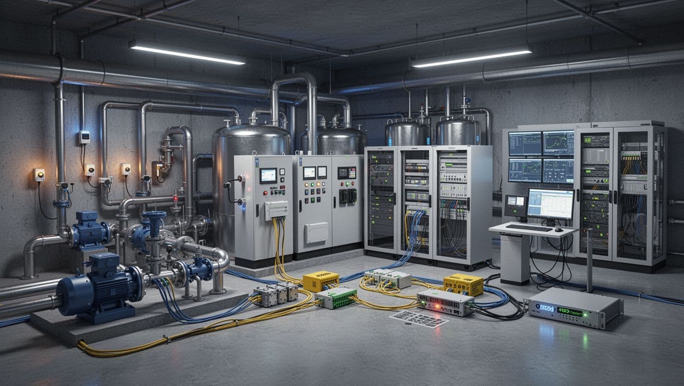
The system begins at the process itself. Sensors measure conditions such as temperature, flow, pressure, level, vibration, position, or chemical concentration. Their signals provide the facts that controllers need before they can make a decision.
Actuators carry out those decisions. They include control valves, motors, pumps, solenoids, heaters, relays, and robotic drives. If a sensor reports that a tank has reached its target level, the controller may close an inlet valve or reduce pump speed.
PLCs and DCS controllers make the fastest routine control decisions. A PLC usually handles machine sequences, discrete inputs and outputs, motion, interlocks, and local PID loops. A DCS controller distributes process-control functions across a plant, which suits continuous operations such as chemical processing, refining, power generation, and water treatment. For background on open architectures and OPC UA connections, see this guide to software-defined automation architecture.
Above those controllers, SCADA servers collect status, alarms, and measurements from remote or distributed equipment. They also provide supervisory commands, but local PLC or DCS logic normally keeps the process running when the SCADA connection drops. SCADA is common in utilities, pipelines, water systems, and geographically spread facilities. A useful overview of this role is provided in what SCADA does in industrial systems.
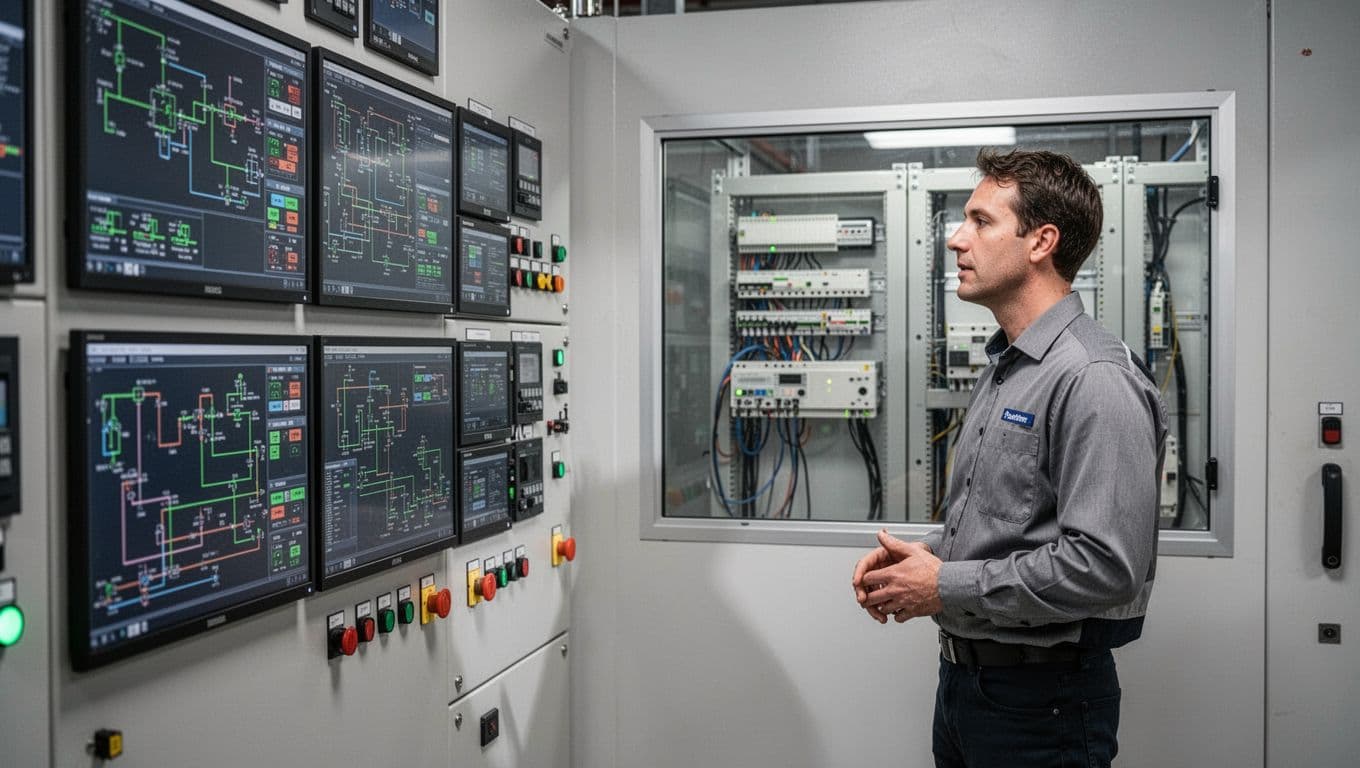
HMIs display the process to operators through graphics, alarm lists, trends, and control screens. Operators can adjust approved setpoints, start equipment, acknowledge alarms, or switch operating modes. However, an HMI generally displays and requests action rather than replacing the controller that executes the control logic.
Data storage and sharing happen in separate layers. A historian stores time-stamped process values, alarm history, production records, and equipment trends. Engineers and reliability teams use that information to investigate faults, compare batches, track energy use, and plan maintenance. Industrial networks connect field devices, controllers, HMIs, servers, and workstations through technologies such as Ethernet-based protocols, fieldbuses, and wireless links.
A safety instrumented system (SIS) provides an independent protection layer. It uses dedicated sensors, a safety logic solver, and final elements to place equipment in a safe state when hazardous conditions occur. For example, an SIS may shut fuel flow after detecting excessive pressure. Routine control optimizes production, while the SIS responds to defined safety risks.
Engineering workstations are where authorized personnel create, test, document, and maintain controller programs, HMI screens, network settings, and safety applications. Because changes made from these systems can affect physical operations, access control, backups, and version management matter.
Finally, edge or IIoT gateways collect selected data and send it to analytics platforms, manufacturing systems, or cloud services. They can translate protocols, normalize tags, buffer data during outages, and run basic analytics near the equipment. A gateway should connect outward without exposing a PLC directly to an untrusted network.
How PLC, DCS, SCADA, HMI, and IIoT Roles Differ
The simplest comparison focuses on where each technology makes decisions and what kind of process it serves:
- PLCs control machines and discrete operations, such as packaging, assembly, conveyors, and robotic cells.
- DCS platforms control large, continuous processes where many loops must operate together across a plant.
- SCADA systems supervise remote or distributed assets, gather telemetry, manage alarms, and send higher-level commands.
- HMIs give operators local or central visibility and approved control over the equipment.
- IIoT systems collect operational data for analytics, reporting, predictive maintenance, and cloud connections.
These categories overlap in modern facilities. A water treatment plant may use PLCs for pump stations, a SCADA server for remote supervision, HMIs in local control rooms, a historian for compliance records, and an IIoT gateway for energy analysis. Choosing an industrial automation control system rarely means selecting one technology alone. The better choice matches each control, safety, operator, and data requirement to the right layer.
How an Industrial Automation Control System Works From Sensor to Action
An industrial automation control system follows a continuous loop: measure the process, evaluate its condition, issue a command, and check the result. The same loop may run several times per second in a machine, while supervisory systems collect the broader picture for operators, engineers, and business applications.
Control Layers, Networks, and Data Flow
The data path usually follows a layered structure:
- Field devices measure temperature, pressure, speed, level, position, flow, or vibration. Actuators, motors, valves, and drives then respond to commands.
- PLCs, DCS controllers, and RTUs evaluate signals against programmed logic, setpoints, sequences, and interlocks. A controller may slow a pump when level rises, open a valve to maintain flow, or stop a motor when a position switch changes state.
- HMIs and SCADA systems show live values, alarms, equipment status, trends, and approved operator controls. An operator can change a recipe, adjust a setpoint, start a sequence, or place equipment in manual mode, subject to permissions and process rules.
- Historians and supervisory servers store time-stamped values, alarm events, recipes, batch records, and calculated performance data.
- MES, enterprise software, analytics platforms, and cloud services use selected production, maintenance, energy, and quality information for reporting and planning.
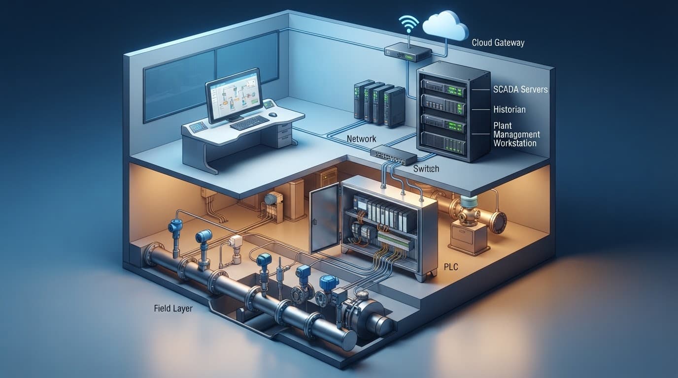
For example, a tank-filling system may read level and pressure sensors every scan cycle. The PLC compares those values with the recipe targets, checks whether permissive conditions are met, and adjusts an inlet valve or pump drive. If the level rises too quickly, the controller can trigger an alarm, close the valve, and record the event for later review.
Communication protocols determine whether these layers can exchange useful data. Industrial Ethernet provides the network foundation, while protocols such as EtherNet/IP, PROFINET, Modbus TCP, and EtherCAT support different control and device requirements. OPC UA adds structured information models, security features, and platform-independent access between controllers, SCADA, historians, and software applications. The OPC interoperability standard explains why common data models matter when equipment comes from multiple vendors.
MQTT uses a broker-based publish/subscribe model, which fits gateways, remote sites, and cloud applications that need lightweight data delivery. It transports messages efficiently, but it doesn’t automatically define what each tag means. For a closer comparison, see this guide to MQTT versus OPC UA for IIoT.
Keep time-critical logic close to the process. A cloud dashboard may help identify rising energy use, but it shouldn’t decide whether a local pump stops.
Analytics and AI applications should usually receive controlled, read-only data through a historian, SCADA server, or edge gateway. That arrangement filters tags, limits access, buffers outages, and protects control logic from poorly tested software. If an application needs to recommend a new setpoint, an authorized operator or supervisory workflow should review that recommendation before it reaches the controller.
Where Safety Systems Fit Into the Architecture
Production control keeps a process within its normal operating range. A safety instrumented system protects people, equipment, and the environment when a hazardous condition requires a defined response. It normally includes dedicated sensors, a safety-rated logic solver, and final elements such as shutdown valves, breakers, or motor disconnects.
An emergency shutdown function may isolate fuel, depressurize equipment, stop rotating machinery, or close process valves. Interlocks prevent unsafe actions, such as starting a pump when a discharge valve is closed or opening a vessel before pressure reaches a safe level. Basic interlocks may exist in PLC or DCS logic, while higher-consequence protective functions belong in an independent SIS or emergency shutdown system.
Safety-rated controllers use certified hardware and software, diagnostics, defined fault behavior, and controlled proof-testing requirements. Their independence matters because a production controller can fail, lose power, or contain a programming error. A separate protective layer reduces the chance that the same fault defeats both control and safety functions.
Engineers determine the required protection through a documented hazard and risk assessment. The result may specify a Safety Integrity Level, such as SIL 2 or SIL 3, for a safety instrumented function. The rating affects sensor architecture, voting arrangements, diagnostic coverage, testing intervals, and final-element design. A control system can support safety functions, but no vendor label replaces the risk assessment, safety lifecycle work, and verification required for the actual process.
Choosing the Right Industrial Automation Control System for Your Plant
The right industrial automation control system depends on the process, plant size, response time, workforce, location, and five-year plan. A compact machine may need a PLC and HMI, while a continuous process with thousands of loops may need a DCS. Many facilities use a hybrid architecture, with PLCs at the machine level, SCADA for supervision, and shared historians or MES connections above them.
Before comparing brands, document the number of control loops, I/O points, remote sites, operators, recipes, safety functions, and required uptime. Also consider the local integrators, spare parts, engineering tools, training, and vendor support available in your region. A familiar platform with strong local expertise can be a better choice than a technically impressive system that nobody nearby can maintain.
Key Features and Standards to Check Before You Buy
Start with controller capacity, scan time, memory, processing headroom, and maximum I/O count. Leave room for expansion, because a controller running near its limits becomes difficult to modify. Check support for discrete, analog, high-speed, motion, remote, wireless, and safety I/O. Redundant CPUs, power supplies, networks, servers, and communication paths may justify their cost in plants where an outage threatens people, product, or equipment.
Alarm management deserves the same attention as control logic. The system should prioritize alarms, record acknowledgments, suppress nuisance alerts, and support operator response procedures. A historian should capture time-stamped values, events, alarms, batch records, and equipment trends at useful resolution. Reporting tools should turn that data into production, quality, energy, maintenance, and compliance reports without forcing engineers to export everything manually.
For recipe-driven production, check batch and recipe functions against ISA-88, also adopted as IEC 61512. For connections between operations and business systems, ISA-95 provides a useful integration model. PLC programming environments commonly align with IEC 61131, while IEC 61850 fits substation and electrical protection applications rather than general factory control.
Open communication matters when equipment comes from several suppliers. OPC UA supports structured, authenticated data exchange, and you can review these OPC UA PLC integration fundamentals before comparing gateway options. MQTT can carry lightweight publish-and-subscribe data from edge devices to brokers and cloud services, but the project still needs a clear tag model and security design.
Access and recovery features should include:
- Role-based permissions for operators, engineers, supervisors, and administrators.
- Audit logs that record configuration changes, logins, setpoint edits, and alarm actions.
- Tested backups for controller programs, HMI projects, recipes, historian databases, and network configurations.
- Recovery procedures that work during server failure, ransomware, hardware replacement, or a communication outage.
- Secure remote access through approved gateways, multi-factor authentication, time limits, and session logging.
- Edge connectivity that filters and buffers data without exposing PLCs directly to business or public networks.
Use the ISA/IEC 62443 cybersecurity standards to guide zones, conduits, security responsibilities, and maintenance practices. Safety integration also requires certified equipment, documented risk assessment, proof testing, and a defined safety lifecycle. A standard alone cannot determine the correct safety architecture for your plant.
Major Vendors and Platform Examples
Several suppliers offer broad portfolios, but no platform wins every application. Examples include Siemens S7 PLCs and PCS 7, Rockwell Automation ControlLogix and PlantPAx, Schneider Electric Modicon and EcoStruxure, and Mitsubishi Electric MELSEC systems.
Process manufacturers may also compare ABB 800xA, Emerson DeltaV, and Honeywell Experion. GE Digital Proficy, AVEVA, and Ignition are common examples in SCADA, visualization, historian, and manufacturing data projects. These products can overlap, especially when a plant combines PLC control with supervisory software and plant-wide reporting.
Treat these names as starting points, not endorsements. Compare the full ecosystem, including engineering licenses, HMI and historian compatibility, cybersecurity updates, migration tools, documentation, training, integrators, spare parts, and service response. A useful comparison of TIA Portal and Studio 5000 shows why engineering workflow and software scope can affect the practical choice.
What Industrial Automation Systems Really Cost
Most projects are quote-based because the price depends on I/O counts, control complexity, environmental ratings, network design, redundancy, site conditions, and integration scope. A software license is only one line in the budget.
Account for controllers, I/O modules, instruments, drives, switches, panels, servers, operator stations, cybersecurity tools, and backup hardware. Engineering, application development, graphics, testing, factory acceptance testing, commissioning, documentation, and operator training can consume a large share of project spending. Travel, production downtime, spare parts, firmware management, upgrades, and lifecycle support add costs after startup.
Upfront cost shows what you pay to install the system. Total cost of ownership also includes energy use, maintenance labor, license renewals, obsolete hardware, unsupported firmware, replacement components, and production interruptions. A low-cost platform may become expensive if only one contractor understands it or if parts require long lead times.
Request a quote that separates capital equipment, engineering, integration, commissioning, training, cybersecurity, and annual support. Then ask how the vendor handles discontinued products, emergency replacement, software recovery, and future expansion. The cheapest initial bid is rarely the cheapest system to operate for the next fifteen years.
Implementing and Testing the System Without Disrupting Production
A careful implementation protects production while turning the selected design into a working industrial automation control system. Start with process requirements, then move through asset inventory, network design, control philosophy, cybersecurity requirements, procurement, programming, testing, commissioning, training, and maintenance planning.
Document every control change before anyone downloads it to a live controller. Whenever possible, schedule cutovers during planned downtime, isolate the affected equipment, and keep a tested rollback plan ready. Production pressure can make shortcuts tempting, but an undocumented change can leave operators and technicians guessing when the next fault appears.
Plan the Architecture, Asset Inventory, and Integration Points
Before configuration begins, create an asset inventory that covers the complete operating environment. Include:
- PLCs, DCS controllers, remote terminal units, and I/O panels.
- DCS nodes, HMI stations, SCADA servers, historians, and alarm servers.
- Safety instrumented systems, emergency shutdown panels, and fire and gas systems.
- Engineering workstations, operator stations, servers, switches, gateways, and backup appliances.
- Remote equipment, remote sites, wireless devices, drives, smart instruments, and IIoT gateways.
The inventory should record each asset’s location, owner, firmware, network address, role, backup status, support contract, and replacement plan. It also needs to show dependencies. A failed switch may affect a controller, an HMI, a historian, and a remote pump station at the same time.
Next, define the system’s information model. Agree on tag names, units, scaling, descriptions, alarm priorities, deadbands, timestamps, and quality states. Assign ownership for each data group so operators, controls engineers, maintenance teams, IT staff, and business users know who can change or approve it.
Map the network into zones and conduits before connecting devices. Identify control zones, safety zones, supervisory servers, business networks, wireless segments, and approved remote access paths. Remote connections should pass through authorized gateways with multi-factor authentication, time limits, logging, and controlled permissions.
Also document interfaces with MES, ERP, maintenance management, reporting, quality, and energy systems. Define which system owns each value, how often data moves, what happens during a communication outage, and whether the connection is read-only. For complex projects, simulate control systems before commissioning to expose sequence and integration problems before site work begins.

Use FAT, FIT, SAT, and SIT to Find Problems Early
Testing works best as a series of gates, not one frantic check at startup. Each gate should use approved procedures, expected results, evidence, defect records, and sign-off requirements.
- Factory acceptance testing (FAT) checks the configured system before shipment. Test sequences, graphics, tags, alarms, interlocks, recipes, user roles, controller behavior, backups, and basic failover in the vendor’s facility.
- Functional integration testing (FIT) checks whether subsystems work together before shipment. It can cover PLC-to-SCADA communications, redundant servers, safety interfaces, historian collection, and connections between equipment supplied by different vendors.
- Site acceptance testing (SAT) verifies the installed system at the plant. Confirm wiring, loop checks, field signals, device ranges, network settings, alarm annunciation, cabinet power, backups, and operator procedures.
- Site integration testing (SIT) tests the complete operational chain at the facility. Run production sequences, recipes, interlocks, safety functions, communications failures, failover, restart behavior, recovery procedures, and interfaces with MES or maintenance systems.
IEC 62381:2024 acceptance testing guidance provides requirements and checklists for FAT, FIT, SAT, and SIT in process-industry automation projects. Keep testing separate from uncontrolled commissioning work, since acceptance tests alone don’t replace loop checks, startup activities, or MES validation.
Correct defects in a controlled environment, retest the failed case, and record the final result. Before handover, train operators and maintenance staff, deliver current drawings and backups, confirm spare parts, and approve a maintenance schedule. The system is ready for production only when the people, procedures, software, and recovery plans are ready with it.
Securing and Maintaining an Industrial Automation Control System
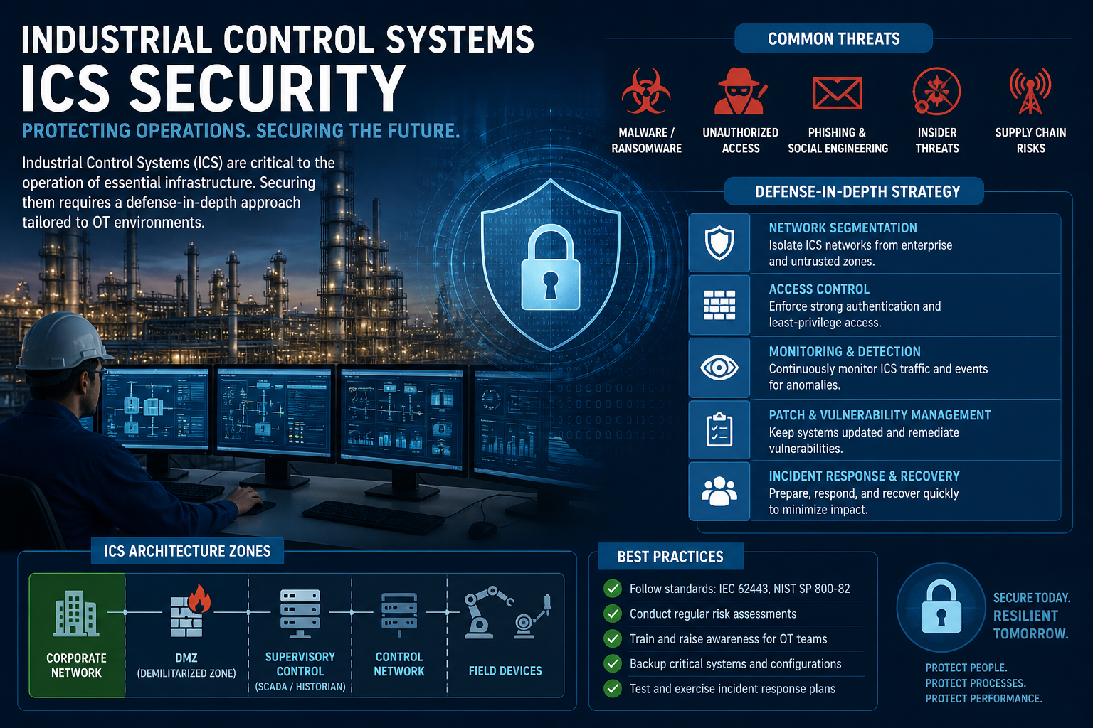
An industrial automation control system needs a security plan that protects safety, availability, and process integrity, not only confidential data. A stolen spreadsheet is serious, but an altered PLC routine can stop a conveyor, overfill a tank, damage a motor, or remove a safety interlock.
Connected systems also widen the attack surface. IT networks, engineering workstations, vendor laptops, cloud platforms, wireless devices, and remote-access gateways may now exchange data with controllers that once operated in isolation. NIST addresses this difference in SP 800-82 Rev. 3, which focuses on OT security while accounting for performance, reliability, and safety requirements.
The Biggest Operational and Cybersecurity Risks
Unauthorized PLC logic changes are among the most serious threats because they can alter machine sequences, alarm limits, interlocks, or shutdown behavior. A small change to a timer or scaling value may produce defective batches, unexpected motion, or unsafe pressure. Engineering workstations therefore need individual accounts, change approval, version control, and audit records.
Weak credentials create another easy entry point. Default passwords, shared administrator accounts, and old vendor logins make it difficult to identify who changed a setting. They also allow one compromised account to reach far more equipment than the user needs. Use unique credentials, role-based permissions, and multi-factor authentication wherever the platform supports it.
Flat networks make the damage spread faster. When every PLC, HMI, server, and maintenance laptop can communicate freely, an attacker who reaches one device may move across the entire plant. Separate control zones from enterprise networks, then restrict traffic through documented conduits, firewalls, and an OT DMZ. The ISA/IEC 62443 standards provide a useful framework for zones, conduits, access control, and lifecycle responsibilities.
Remote access needs the same discipline. Exposed VPN services, permanent vendor tunnels, direct internet connections, and unattended remote tools can provide a path into live equipment. A safer arrangement uses approved gateways, individual accounts, limited permissions, session logging, and access that starts only after plant approval and ends when the work finishes. Review these secure remote access practices before giving outside personnel access to a control network.
Older controllers and HMIs may lack current encryption, security updates, or modern authentication. Weak vendor support makes the problem harder when the manufacturer stops issuing patches, discontinues spare parts, or provides incomplete migration guidance. Unsafe cloud connections can expose process data or create an unexpected path back toward control assets.
Poor backups create a second failure after the first incident. If the only copy of a PLC program sits on a compromised engineering laptop, recovery may depend on guesswork. Incomplete commissioning tests create similar risk because teams may never discover incorrect alarm priorities, failed interlocks, bad failover behavior, or unsafe restart sequences.
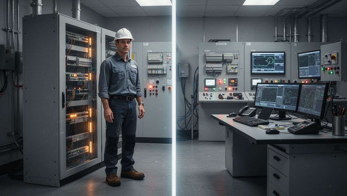
In OT, integrity and availability are safety concerns. A system can protect confidential data yet still fail if it allows an unauthorized control change.
A Practical Security and Lifecycle Checklist
Security begins before installation and continues through upgrades, maintenance, and retirement. Plant teams should keep the following activities tied to normal operating procedures:
- Remove default credentials, create named user accounts, and assign permissions by job role.
- Review PLC project files, HMI applications, recipes, safety programs, and network configurations for unexpected changes.
- Apply vendor patches during approved downtime after testing them on representative hardware or a staging system. If a legacy device cannot be patched, add compensating controls such as isolation, restricted access, and closer monitoring.
- Block unnecessary traffic between control zones, and separate plant networks from enterprise systems with only the required connections.
- Route remote maintenance through a controlled gateway. Require approval, multi-factor authentication, time limits, least privilege, and session logs.
- Monitor controller events, logins, configuration changes, failed access attempts, and remote sessions. Passive monitoring is often safer than aggressive scanning on live equipment.
- Back up controller programs, HMI projects, recipes, historian data, firmware files, license keys, network settings, and system documentation. Store protected copies offline or outside the affected network.
- Test restoration on replacement hardware or a recovery system. A backup that has never been restored is an assumption, not a recovery plan.
- Track firmware versions, vendor support dates, spare parts, engineering software, and replacement options throughout the system’s service life.
- Train operators, maintenance staff, engineers, IT personnel, and vendors to recognize unsafe changes, suspicious access, and unusual equipment behavior.
NIST SP 800-82 Rev. 3 and IEC 62443 both treat security as lifecycle work. Assess the assets and risks, build controls into the design, maintain them through change management, and rehearse incident response and recovery. That approach keeps protection aligned with production instead of adding security after the system is already difficult to change.
Conclusion
The best industrial automation control system isn’t the one with the longest feature list. It fits the process, protects people and equipment, connects cleanly with required tools, gives operators useful information, and remains supportable for years without adding needless complexity. For some plants, that may mean a conventional PLC or DCS architecture; others may benefit from open software-defined automation.
Begin with process goals and asset risks. Then compare architectures, vendors, lifecycle costs, testing plans, and cybersecurity requirements before making a purchase, using NIST SP 800-82 Rev. 3 and ISA/IEC 62443 to guide the security work. A well-chosen control system is one operators can trust during normal production, equipment faults, and recovery.