Why do two transformers with the same components have such different service lives? One runs reliably, while the other keeps overheating, tripping, and producing gas alarms.
The difference becomes clearer when you look at four connected systems, because a weakness in one can create problems in another. Let’s look at how those systems work in a typical oil-filled power transformer, what each one protects, and what happens when it is neglected.
Table of Contents
The Four Jobs a Power Transformer Must Do
A power transformer’s basic job sounds simple: take electrical power at one voltage and deliver it at another. In practice, it must perform several jobs at the same time to keep operating safely.
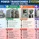
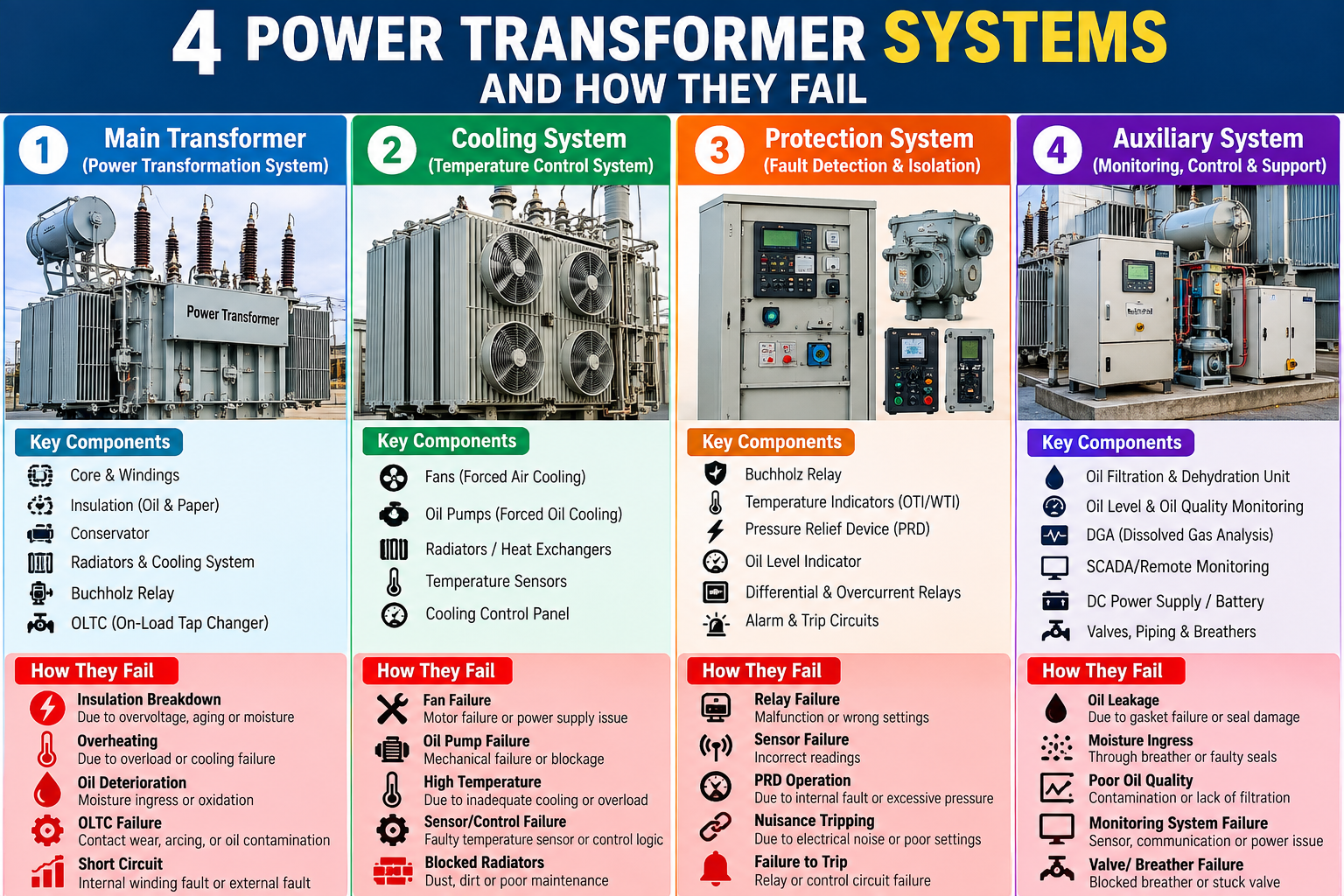
The components fall into four functional systems:
| System | Main components | Job |
|---|---|---|
| Power transformation | Core, windings, and insulation | Transfer power between voltage levels while maintaining electrical separation. |
| Oil and moisture control | Tank, oil, conservator, and breather | Accommodate oil expansion and contraction and help keep insulation dry. |
| Connection and voltage control | Bushings and tap changer | Connect the transformer to the grid and adjust its voltage ratio. |
| Cooling and protection | Radiators, fans, pumps where fitted, Buchholz relay, and pressure devices | Remove heat and respond to abnormal internal conditions. |
These systems share the same equipment and affect the same insulation. Their condition determines how well the transformer handles electrical stress, moisture, heat, and internal faults.
Think of the human body. The heart pumps blood, the lungs handle breathing, the hands connect with the outside world, and the skin and immune system provide protection. The transformer also has different systems working within one asset.
Equipment designs vary. Not every transformer has an on-load tap changer, oil pumps, or the same protection arrangement.
System 1: Core, Windings, and Insulation Transfer Power
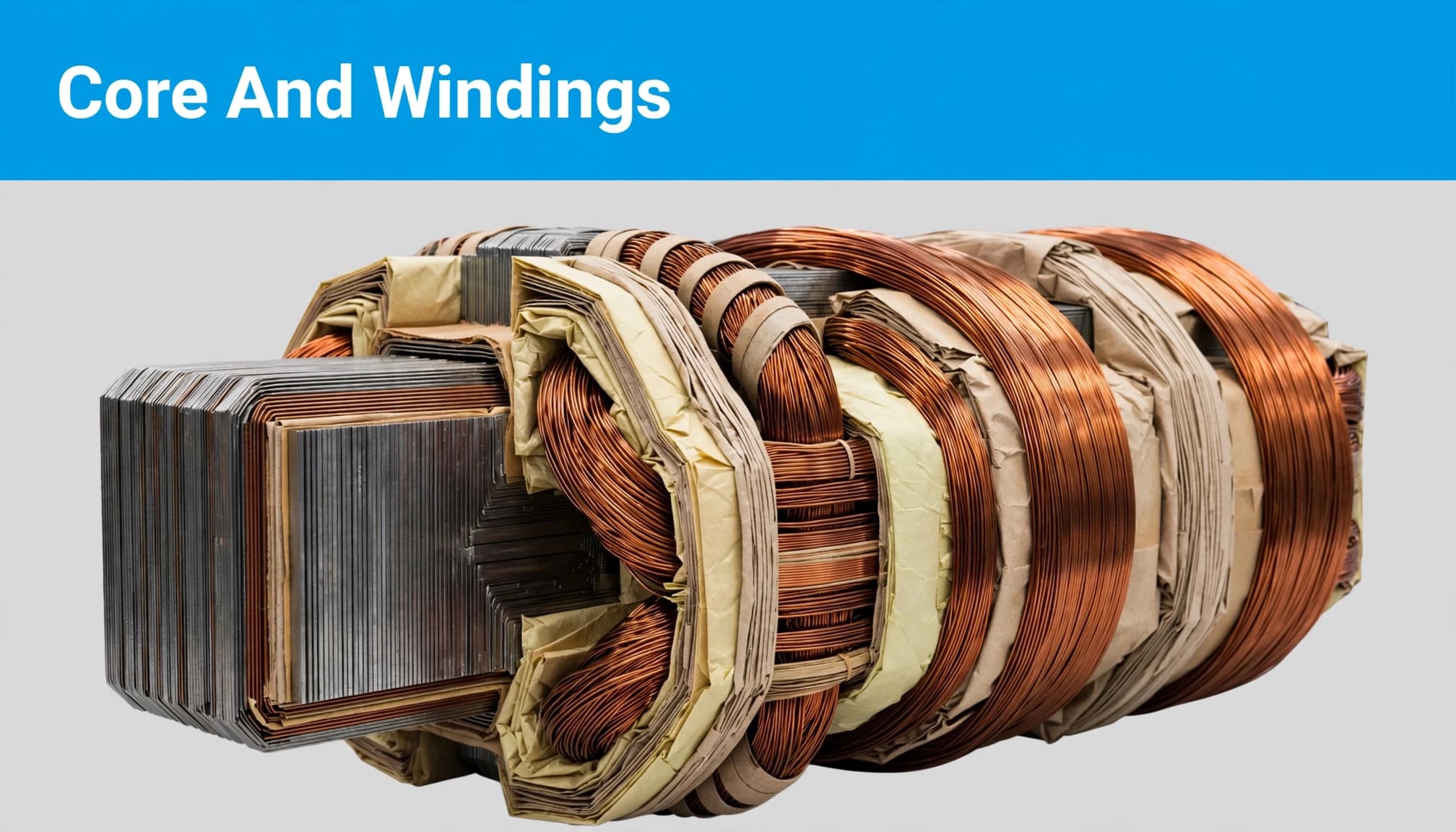
The core, windings, and insulation are the heart of the transformer. Each has a defined function:
- The laminated core carries the magnetic flux.
- Copper or aluminum windings carry the current.
- Solid and liquid insulation keep the electrically active parts separated.
Electrical power transfers between voltage levels through electromagnetic induction. The core provides the magnetic path, while the windings enable the voltage transformation.
That separation matters. If the insulation fails, parts that should remain electrically isolated can short-circuit.
Why Heat and Moisture Shorten Insulation Life
Power transformation also produces losses and heat. Core losses occur whenever the transformer is energized, while winding losses rise with load current.
This heat passes into the oil and the insulation around the windings. The oil must carry it away, and the cooling system must release it.
Insulation doesn’t always fail suddenly. Heat and moisture age it over time, particularly the paper insulation around the windings.
Keeping this system cool and dry supports longer service life. Running it hot and wet accelerates deterioration. That connects the transformer’s electrical function directly to its moisture-control and cooling systems.
System 2: The Tank, Oil, Conservator, and Breather Protect Insulation
The main tank contains the core and windings immersed in oil. Transformer oil performs two jobs: it provides electrical insulation and carries heat away from the active parts.
As the load rises, the oil heats up and expands. When the load falls, the oil cools and contracts. The conservator provides space for those changes in oil volume.
In a conventional free-breathing conservator, part of the vessel contains oil and the remaining space accommodates the changing level. Expansion raises the oil level; contraction lowers it.
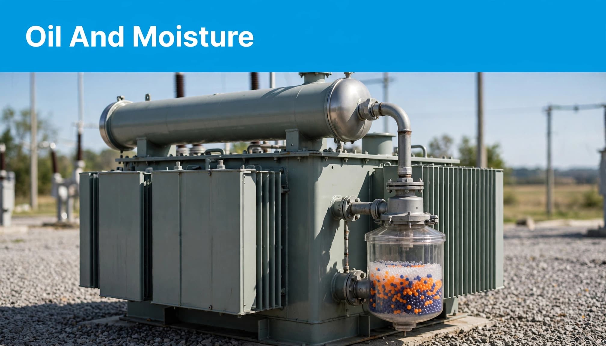
How the Breather Limits Moisture Entry
The catch is the air entering a free-breathing conservator. Atmospheric air can carry moisture, and moisture harms the insulation system.
The incoming air passes through a breather containing silica gel. The gel absorbs moisture before the air reaches the conservator.
Many modern power transformers use a bladder or diaphragm inside the conservator to separate the oil from atmospheric air. The construction differs, but the objective stays the same: keep moisture away from the insulation.
The operational concern is the condition of the breathing path and its moisture barrier. The conservator’s ability to accommodate changing oil volume is only part of the job.
What Happens When Moisture Control Is Neglected
Moisture control becomes less reliable when the breather or conservator arrangement deteriorates. The warning conditions include:
- Silica gel is saturated and hasn’t been replaced or regenerated; some traditional breathers show an indicator-color change.
- The conservator bladder or diaphragm is damaged.
- The oil level is low and the cause hasn’t been investigated.
These conditions can give moisture an easier path into the insulation system.
Moisture reduces dielectric strength, meaning the insulation has less ability to withstand electrical stress. It also accelerates the aging of paper insulation.
As that insulation margin weakens, the risk of discharge or breakdown increases. If an internal fault or overheating condition develops, it can generate gas that is eventually detected by the transformer’s protection.
The visible symptom may be a gas alarm. The original problem may have started in the breathing system.
System 3: Bushings Connect High Voltage Through the Tank
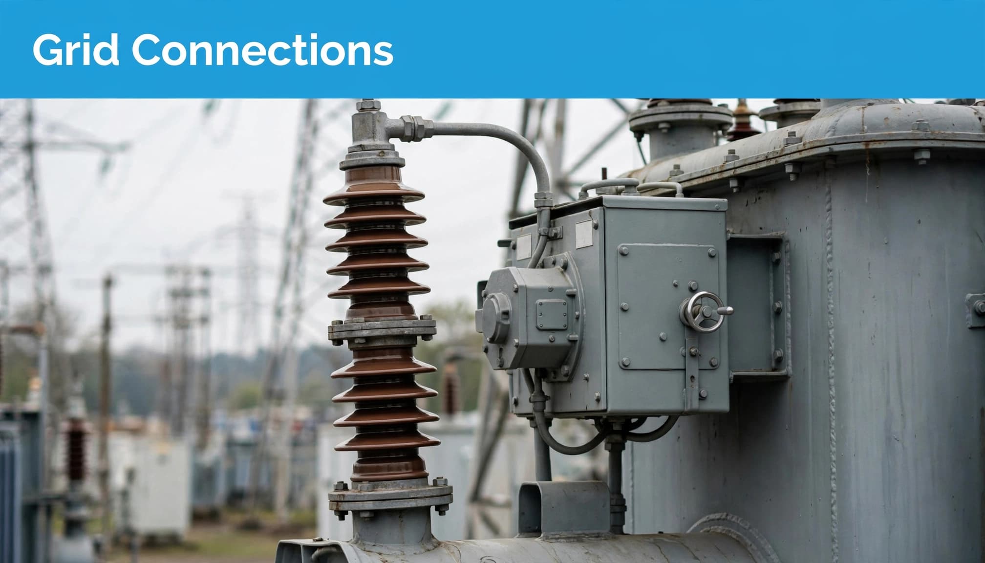
A high-voltage conductor must enter the transformer without making electrical contact with the grounded tank wall. The bushing provides that insulated passage.
A conductor runs through the center, with insulation around it. The external sheds help manage exposure to rain and pollution.
The comparison is a pipe passing through a house wall. If the opening around that pipe isn’t sealed properly, rain can enter. A bushing is the sealed, insulated entry for high voltage.
Where a Bushing Can Become the Weakest Point
A cracked seal, a dirty and wet surface, or an abnormal internal oil level in an oil-filled bushing can weaken this entry point.
Bushing inspection therefore includes the surface condition, tracking marks, oil leaks where applicable, and uneven heating. Looking only at the main tank misses the point where the outside environment meets the internal insulation system.
The bushing must maintain that electrical separation under operating conditions. Damage or contamination at this boundary can make an otherwise healthy transformer vulnerable.
How Tap Changers Keep Secondary Voltage Within Its Band
Grid voltage moves up and down, and load conditions change. The transformer’s secondary voltage still needs to remain within its defined band.
A tap changer adjusts the transformer ratio by changing the number of active winding turns. This is the tap changer’s role in voltage regulation.
An on-load tap changer (OLTC) makes that adjustment while the transformer is carrying load, without interrupting the supply. An off-load tap changer requires an outage before the tap position is changed.
The distinction is operational: one supports voltage adjustment during service, while the other requires the supply to be disconnected. Not every power transformer has an OLTC; its selection depends on the application.
What Stresses an On-Load Tap Changer
Each tap change transfers load current between tap positions. In conventional oil-switching OLTC designs, the switching contacts operate in insulating oil.
The oil in that switching compartment can deteriorate, contacts need attention, and the drive mechanism can jam. Maintenance requirements depend on the design, including whether the OLTC uses oil-switching contacts or vacuum interrupters.
For conventional oil-switching equipment, attention centers on oil condition, contacts, the drive mechanism, and operation count. Manufacturer documentation, such as Hitachi Energy’s UC tap-changer document, is specific to the equipment design.
An OLTC is an electromechanical system within an electrical asset. Its moving parts and switching components have their own operating stresses.
System 4: Radiators, Fans, and Pumps Remove Heat
The heat produced in the core and windings must leave the tank.
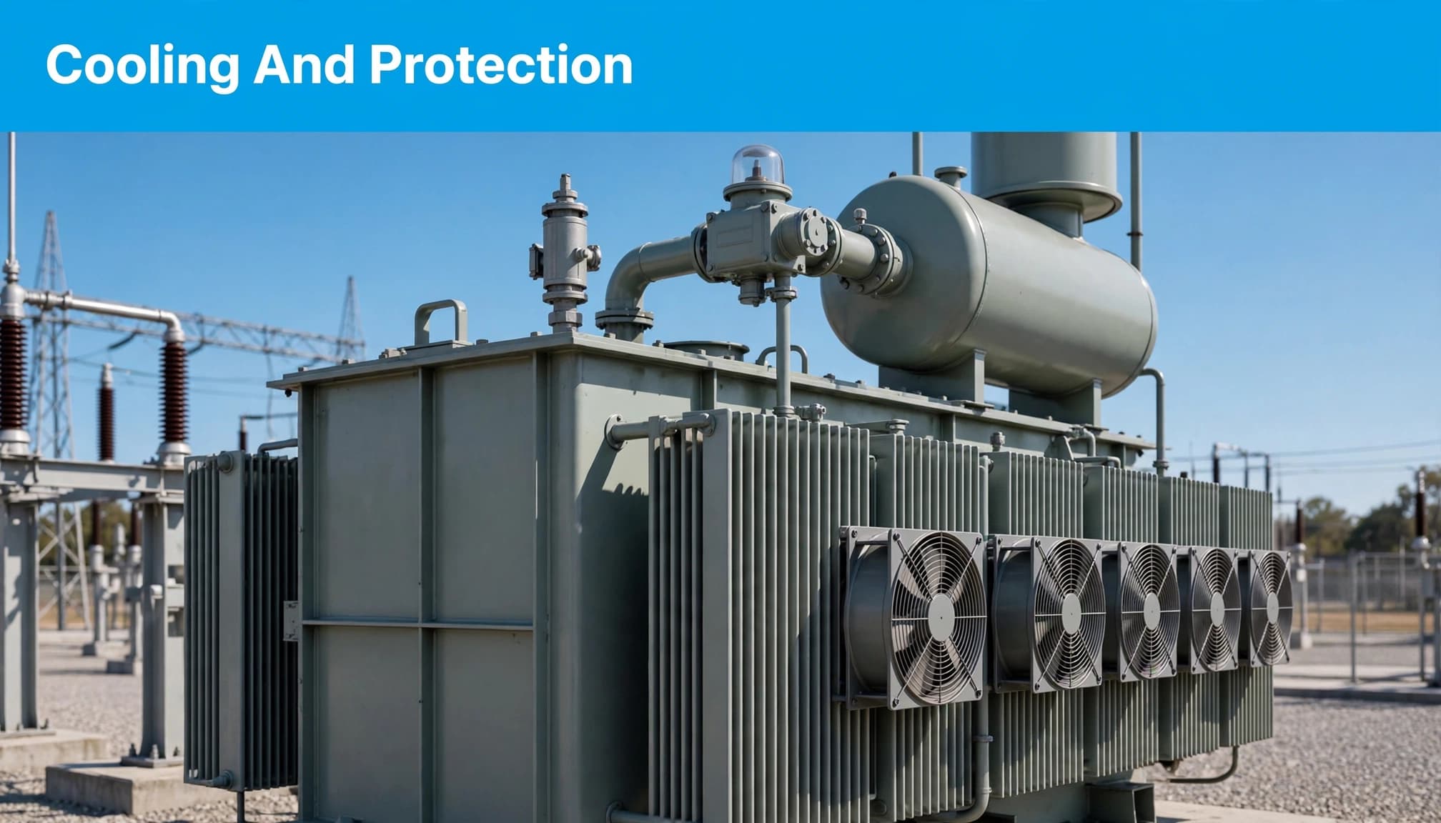
In a small distribution transformer, natural oil and air circulation through the radiators may provide the required cooling. Hot oil rises, circulates through the radiator assembly, cools, and returns.
Many larger power transformers also operate at part of their rating using natural oil and natural air circulation. As loading increases, fans can switch on to move more air across the radiators and increase cooling capacity.
Some large transformer designs also use pumps to circulate the oil. Additional cooling stages can come into operation as the load rises.
Why a Running Transformer Can Still Have a Cooling Problem
Failed fans, radiator valves left closed or partly closed after maintenance, and fins choked with dust can reduce heat removal.
The transformer may continue running. Its temperature can still rise above what the healthy cooling arrangement would support.
A transformer can remain in service with impaired cooling while its insulation ages faster. Continued operation doesn’t prove that heat removal is adequate.
This brings the effect back to System 1. The cooling equipment is outside the winding assembly, but the paper insulation inside pays the price for higher temperature.
How Buchholz Relays and Pressure Devices Respond to Faults
Cooling manages operating heat. Protection devices respond when abnormal internal conditions develop.
On a conservator-type transformer, the Buchholz relay is installed in the pipe between the main tank and the conservator. Its basic operation distinguishes gradual gas accumulation from a sudden oil surge.
Gas Accumulation Produces an Alarm
An incipient internal fault or local overheating can decompose oil or insulation and generate gas. The bubbles rise and collect in the Buchholz relay.
As gas accumulates, the alarm element operates and sends an alarm to the control system. This gives an indication of a developing internal condition.
A Severe Oil Surge Produces a Trip
A severe internal fault can create a sudden movement of oil toward the conservator. That rapid oil surge operates the Buchholz relay’s trip element.
The basic distinction is gas accumulation for alarm, rapid oil movement for trip. These responses relate to different internal conditions, even though they occur in the same relay assembly.
Pressure Detection and Pressure Relief Have Different Jobs
Depending on the design, a transformer may also have a sudden-pressure relay and a pressure-relief device.
The sudden-pressure relay detects an abnormal rapid rise in internal tank pressure and sends a protection signal.
The pressure-relief device physically releases excessive internal pressure to help prevent tank damage. One detects and signals; the other relieves pressure.
These devices form part of the transformer’s last line of defense when abnormal internal conditions develop. The exact arrangement varies with the transformer design.
How a Problem in One System Appears in Another
The four systems are easy to separate in a diagram. In operation, their effects are connected.
Poor moisture control can weaken insulation. Weakened insulation has less margin against electrical stress, which increases the risk of discharge or breakdown. A developing internal fault or overheating condition can then generate gas and produce a Buchholz alarm.
A loose internal connection provides another path: it can create local heating and gas that the protection detects. The protection signal appears in one system, while the originating defect is elsewhere.
The same relationship applies to cooling. Failed fans or restricted radiators affect heat removal, but the resulting higher temperature accelerates aging in the winding insulation.
This means component condition has to be understood in context. A gas alarm, abnormal heating, or insulation problem can be the outcome of a weakness in another system.
Transformer Reliability Depends on the Whole System
Two transformers can have the same list of parts and still experience very different service lives. What matters is how well those parts perform their connected jobs under operating conditions.
The core and windings depend on dry insulation and effective heat removal. Connections and voltage controls introduce their own stresses, while protection responds to abnormal conditions.
A weakness in one system can become a failure in another. That is why a transformer makes more sense as four connected systems than as a collection of separate components.