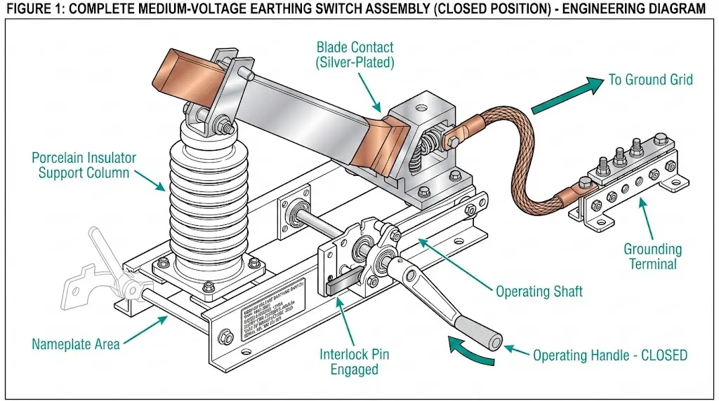
A transmission line can be switched off and still hold a surprise. Current flow may stop, yet residual charge can stay on the isolated section.
That hidden charge is why earth switches matter. A circuit breaker can interrupt current, and a disconnector can give you a visible isolation gap, but neither one drains leftover charge by itself.
Once that job becomes clear, the ratings, classes, and high-speed versions of earthing switches make much more sense.
Why isolation alone is not enough
In switchgear, each device has a different job. A circuit breaker opens and closes under normal conditions, and it can also interrupt fault current. A disconnector creates a visible gap so people can see that a section is isolated for maintenance.
Still, isolation does not always mean the conductor is free of charge. That is the gap an earth switch fills.
A simple water system shows the problem well. When a pump runs, water flows through a pipe. When the pump stops, the flow stops too, but some water remains inside the pipe. The pipe is not empty until that water gets a path out.
An isolated electrical conductor can behave in a similar way. Disconnect the line from both ends, and power no longer flows through it. Even so, charge can remain on that isolated section for a time. If someone touches it during maintenance, that charge may find a path to ground through the person’s body.
This quick comparison makes the different roles easier to see:
| Device | Main job | Used under normal load? | What it does not do by itself | | | | | | | Circuit breaker | Switches and interrupts current, including fault current | Yes | Does not provide visible isolation or drain residual charge | | Disconnector | Creates a visible isolation gap | No, not for load switching in normal operation | Does not remove trapped or residual charge | | Earthing switch | Connects the isolated part of the circuit to ground | No | Does not carry normal load current continuously |
The short version is simple: the breaker stops current, the disconnector isolates, and the earthing switch makes the isolated section safe to work on.
What an earthing switch does after a circuit is isolated
Take a transmission line as an example. Once the line is disconnected at both ends, it no longer carries power from source to load. Yet the isolated section may still hold residual charge. The same issue can appear on a busbar inside a substation, not only on a long line.
That matters during maintenance. An open gap is helpful, but grounded metal is what removes the leftover electrical charge.
When the earthing switch closes, it connects the isolated conductor directly to earth, or ground. That gives the residual charge a low-resistance path away from the equipment. Instead of waiting on the conductor, the charge drains safely to ground.
After that, the isolated part is in the condition maintenance crews want. It is disconnected from the source, visibly isolated, and grounded. In everyday language, “earth switch” and “grounding switch” mean the same thing.
This is why the device matters so much in substations and switchgear. Without it, a worker may face charge that is no longer part of the active system, but is still dangerous. With it, that stored charge has somewhere safe to go.
The same safety logic shows up in field work on distribution gear. If you work around RMUs, this guide on how to maintain a ring main unit gives more context on safe isolation and maintenance practice.
What IEC 62271-102 says and what the ratings mean
For high-voltage AC disconnectors and earthing switches, the standard most often cited is IEC 62271-102. The IECEE overview of IEC 62271-102:2018 covers the document scope and confirms that earthing switch functions are included.
The standard definition is straightforward. An earthing switch is a mechanical switching device for earthing parts of a circuit. It must be able to withstand current for a specified time under abnormal conditions, such as a short circuit, but it is not required to carry current under normal circuit conditions.
Normal current is not its job
An earthing switch does not sit closed during normal service. Because of that, it does not need continuous current-carrying capacity in the same way a busbar, breaker, or disconnector does.
If a system carries 2,000 A in normal operation, that does not mean the earthing switch is built to carry 2,000 A continuously. That is simply not the role of the device.
An earthing switch is for grounding an isolated circuit section, not for carrying load current in normal service.
This point sounds simple, but it prevents a lot of confusion. Many people first meeting switchgear assume every switch-like device must carry normal current. An earthing switch is different.
It may need to withstand or make fault current
Although it does not carry normal load current, it may still need strong fault-duty ratings. One of those is short-time withstand current. If the earthing switch is closed and a fault occurs, it may need to carry that fault current for a short period, often for 1 second or 3 seconds.
Another rating is making capacity. This matters when the switch must close onto an existing fault condition and connect it to ground. Not every earthing switch has that ability, so it cannot be assumed.
Manufacturers prove these ratings through type testing. In practice, that means the switch is tested for the duty it claims on its nameplate. If a model is rated for short-time current or making duty, that claim has to be backed by testing, not guesswork.
The two earthing switch designs you will see most often
Earthing switches usually appear in one of two layouts. Some are independent devices. Others are built into another switching device.
Independent earthing switches
An independent earthing switch is its own separate unit. You might find it mounted inside a panel, or in some cases in a dedicated earthing compartment or panel arrangement. Its job is direct and clear: once the circuit section is isolated, this device grounds it.
This layout is easy to understand because the earthing function stands on its own. In training and maintenance, that makes the device role easy to explain.
Combined earthing switches
A combined earthing switch is integrated with another device. The most common example is an earthing switch paired with a disconnector. In that arrangement, the same assembly handles visible isolation and grounding, although the functions remain distinct.
Some disconnecting circuit breaker designs also include an integral earthing switch. That setup can reduce the number of separate devices in the bay while keeping the grounding function available when needed.
From an operator’s point of view, the main idea stays the same in both layouts. First isolate the circuit section. Then ground it. The packaging changes, but the safety purpose does not.
E0, E1, and E2 classes are not small details
IEC classifies earthing switches by their short-circuit making performance. That classification matters because some earthing switches can close onto fault current, while others cannot.
This table gives the quick picture:
| Class | Short-circuit making operations | Practical meaning | E0 | None | No short-circuit making capacity | | E1 | Two operations | Can perform two short-circuit making operations | | E2 | Five operations | Can perform five short-circuit making operations |
The takeaway is direct. An E0 earthing switch is not intended to close onto an existing fault. If someone uses it that way, the switch can fail and the situation can get worse.
An E1 switch can perform two short-circuit making operations. An E2 switch can perform five. Those classes are not marketing labels. They describe tested fault-making capability.
Because of that, the nameplate matters. Before an earthing switch is selected or operated for a fault-related duty, its class needs to match the intended use. If the switch has no making capacity, it cannot be treated like one that does.
People often focus on voltage and current first, which makes sense. Still, the E-class rating can be just as important when fault conditions enter the picture.
How high-speed earthing switches limit internal arc damage
Earthing switches do more than discharge residual charge after isolation. Some are built to act as protective devices during internal faults inside switchgear.
This comes up in medium-voltage panels and in gas-insulated switchgear. If an internal arc develops inside the enclosure, energy rises fast. Light, heat, pressure, and fault current can put both equipment and nearby workers at risk.
A high-speed earthing switch is designed for that moment. Sensors watch for abnormal conditions, such as fault current or the light produced by an internal arc. Once the system detects the fault, it sends a command to the high-speed earthing switch.
The switch then closes extremely fast and creates a controlled short-circuit path to ground. That diverts the fault current away in a way that helps protect the switchgear assembly and reduces danger around it. In many designs, this action is faster than the response of the main circuit breaker.
Some high-speed earthing switches are built in vacuum pole units with their own operating mechanism. The hardware changes by design, but the purpose stays the same: move the fault current to ground as fast as possible.
If you work with enclosed medium-voltage gear, this switchgear inspection safety guide adds useful context on testing and safe work around metal-clad equipment.
Final thoughts
Opening a circuit does not always make it safe to touch. Grounding the isolated section is what removes residual charge and closes the safety gap between isolation and maintenance.
That is the real purpose of an earth switch. In standard switchgear, it drains trapped charge to ground. In high-speed designs, it can also help limit damage during internal arc faults.
If one idea stays with you, let it be this: an isolated conductor may still hold charge until it has a path to earth.