Flip a light switch and power feels simple. Behind that simple act sits a chain of equipment that switches circuits, measures conditions, isolates faults, and keeps the rest of the system alive.
That full package is switchgear. Once that idea clicks, substations, distribution panels, and even the breaker board in a building start to make far more sense.
What switchgear really means
People often use the word switchgear as if it means only switches or breakers. In practice, the term is much wider. Switchgear includes the devices that switch a circuit, protect it during faults, measure electrical values, and support control of the system.
That matters because a power system is never a single straight line. Electricity may start at a generating station, get stepped up for long-distance transmission, pass through more than one substation, step down again for distribution, and then split across many feeders before it reaches homes, buildings, and industrial loads. Add wind, solar, and HVDC links, and the picture gets even more layered.
At every stage, someone has to connect, disconnect, protect, and monitor the circuit. That is where switchgear comes in.
A simple home circuit shows the same idea on a smaller scale. The wall switch turns a light on and off. The MCB protects the wiring during a short circuit or overload. The meter records how much electricity the site uses. A power system uses the same logic, only with much larger equipment and much higher fault levels.
IEC defines switchgear as a general term that covers switching devices and their combination with associated control, measuring, protective, and regulating equipment, along with assemblies, interconnections, accessories, enclosures, and support structures. Schneider Electric’s switchgear overview uses the same broad idea.
Switchgear is the whole fault-clearing and control package, not only the switch itself.
The devices that sit inside switchgear
A typical switchgear lineup can include circuit breakers, switches, fuses, isolators or disconnectors, protective relays, control panels, lightning arresters, current transformers, voltage transformers, and other related parts.
Each piece has a job. The breaker opens and closes the circuit. The relay detects abnormal conditions. The current transformer and voltage transformer scale system values down to levels that measuring and protection devices can use safely.
Because of that, switchgear improves both reliability and safety. A fault can be detected and cleared fast. The damaged section can be isolated. Meanwhile, healthy sections of the system can stay energized.
How switchgear clears a fault
A circuit breaker can open during normal operation, such as maintenance or routine switching. It can also open during abnormal conditions, such as a short circuit. Still, the breaker does not “know” on its own when trouble starts.
That sensing job belongs to the relay. The relay watches system conditions and sends a trip command when it detects a fault.
Current transformers and voltage transformers make that possible. A relay cannot take direct input from transmission-level current or voltage. A current transformer reduces current to a smaller, usable value. A voltage transformer does the same for voltage. The relay reads those inputs, decides whether something is wrong, and trips the breaker if needed.
Once those parts are seen as one working set, the term switchgear stops sounding vague. It becomes a practical way to describe the control and protection layer around an electrical circuit.
The three main switchgear categories
Switchgear is commonly grouped by voltage level. That simple split helps explain where each type fits in the power system.
The breakdown below matches the standard LV, MV, and HV grouping found in many industry references, including GW Electric’s summary of switchgear types.
| Category | Typical voltage range | Common part of the system | Notes from the overview | | Low voltage (LV) | Below 1 kV | Secondary distribution, building switchboards, motor control | Often air-insulated, high current levels | | Medium voltage (MV) | 1 kV to 52 kV | Primary distribution, feeder panels, industrial distribution | Factory-assembled panels are common | | High voltage (HV/EHV) | Above 52 kV | Primary and secondary transmission, grid substations | Larger clearances, outdoor yards or compact GIS |
That voltage-based view gives a good first map. The next step is to see how each class behaves in the field.
High-voltage switchgear in transmission systems
High-voltage switchgear sits in the transmission side of the network. In IEC-based systems, anything above 52 kV falls in this group. Common rated voltages include 72.5 kV, 145 kV, 245 kV, 420 kV, and in some systems up to 800 kV, although exact ratings vary by country.
These installations appear where power leaves the generating station and enters primary transmission, and again where voltage steps down into sub-transmission. Typical rated current can reach 4,000 A, while short-circuit ratings may go up to 63 kA.
Because voltages are so high, insulation distance matters a great deal. The gap between phases, and the clearance between live parts and grounded structures, grows with the voltage rating. That is one reason high-voltage yards often look wide and open.
Air-insulated switchgear, or AIS
In high-voltage AIS, air provides the insulation between phases. That naming point matters, because the interrupter itself may still use another medium, such as SF6, inside the breaker chamber.
So, in an AIS substation, the R, Y, and B phases are separated by open air. Since air has lower dielectric strength than insulating gas, the equipment needs more physical spacing. The higher the voltage, the more distance the design requires.
That brings a few clear traits:
- AIS is usually installed outdoors.
- It needs more land than compact alternatives.
- Maintenance demands are higher because equipment sits exposed to weather and pollution.
- Cost is lower than GIS in many cases.
For that reason, AIS remains the most common high-voltage approach in many substations. Circuit breakers, disconnectors, current transformers, and other devices are often laid out as separate pieces of equipment in the yard.
Gas-insulated switchgear, or GIS
In GIS, insulating gas provides the insulation between phases. SF6 has been the most widely used gas for this job because its dielectric strength is much higher than air.
That higher strength allows designers to place parts much closer together. The result is a much more compact switchgear arrangement. A GIS installation can include the circuit breaker, current transformer, voltage transformer, disconnector, earthing switch, busbar section, cable or line connection, and local control cubicle within one metal-enclosed, factory-assembled unit.
This also changes procurement and installation. In a typical AIS yard, utilities can often source breakers, CTs, VTs, and disconnectors from different manufacturers and combine them on site. GIS is different. Because the parts are enclosed and tightly integrated, it is usually supplied as a complete assembly from one manufacturer.
That compact form makes GIS attractive where land is scarce or expensive. Urban substations often use it for that reason. Most GIS installations are indoor, although outdoor versions exist. The tradeoff is cost, because the initial investment is much higher than AIS. The market still uses SF6 heavily in this area, though SF6-free options are also being developed and applied.
Hybrid or mixed-technology switchgear
Hybrid switchgear sits between AIS and GIS. The idea is simple: combine selected GIS parts with selected AIS parts.
A common arrangement uses a dead-tank breaker with AIS disconnectors. That cuts the footprint compared with a full AIS yard, but it does not reach the compact size of full GIS.
This approach fits projects where land is tight, yet a full GIS budget is hard to justify. It is less common than AIS or GIS, but it fills a practical middle ground.
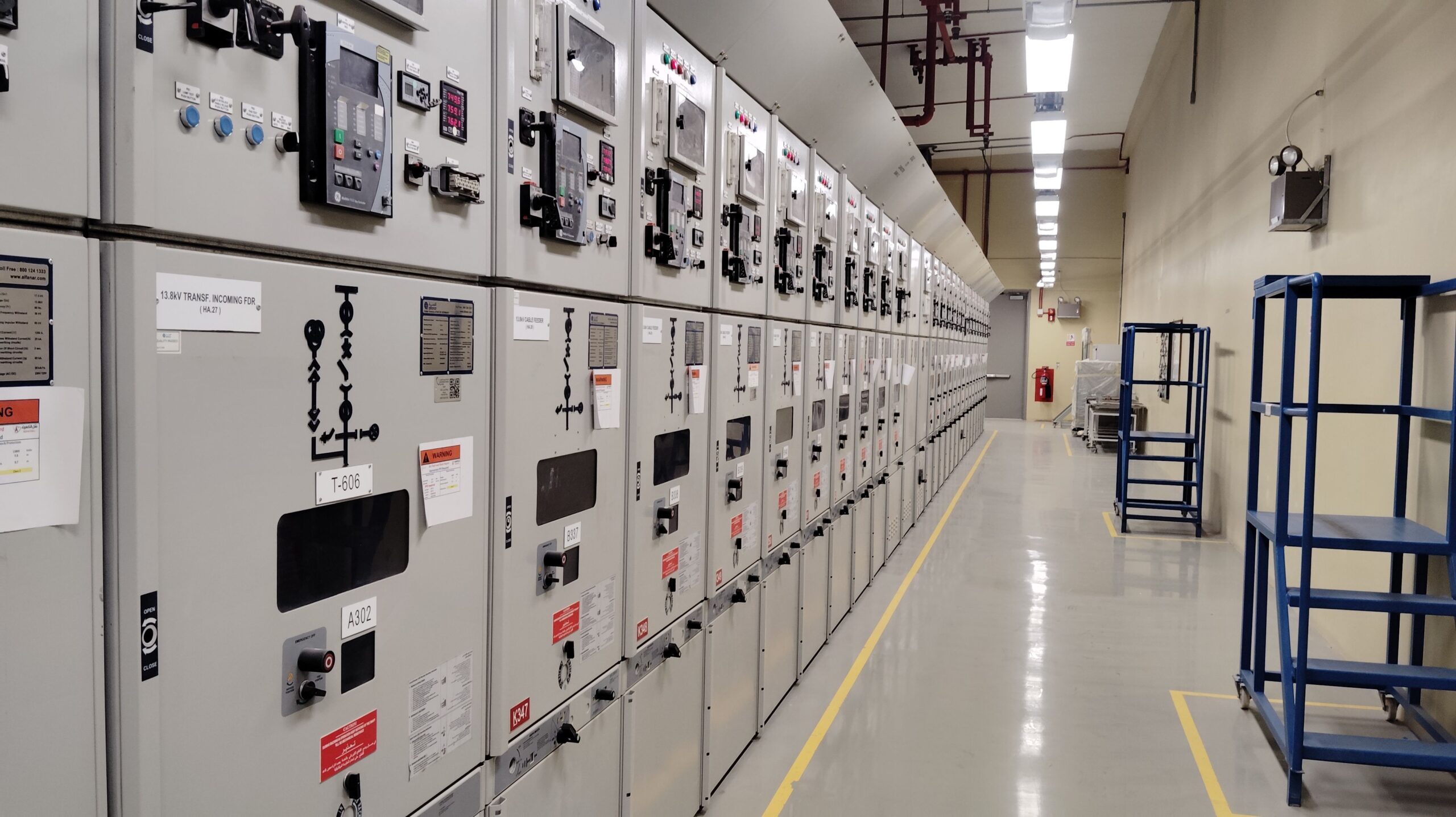
Medium-voltage switchgear in distribution networks
Medium-voltage switchgear covers the range from 1 kV to 52 kV. This is the voltage class found in primary distribution, where incoming supply is split across feeders and sent deeper into cities, plants, campuses, and large buildings. Common system levels in this space include 11 kV and 36 kV.
One key difference shows up right away. MV switchgear is usually factory-assembled in metal-enclosed panels. Instead of building an outdoor yard with separate pieces spread across wide clearances, manufacturers package the equipment inside panels that line up side by side as a switchboard.
A typical lineup includes one panel for the incomer, one for each outgoing feeder, one for the bus coupler, and sometimes a bus riser panel. Rated current often goes up to 4,000 A, and in some cases reaches 5,000 A.
For a closer look at medium voltage switchgear types, including AIS, GIS, VCB, and RMU designs, the classifications line up well with this same structure.
MV air-insulated switchgear
In medium-voltage AIS, air provides insulation between phases and between internal compartments. Because MV levels are lower than HV transmission levels, the equipment can fit inside compact metal-clad or metal-enclosed panels.
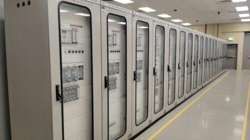
Those panels usually include a busbar compartment, cable compartment, apparatus compartment, current and voltage transformers, and a low-voltage compartment for relays and control wiring. In MV gear, the most common interruption technology is the vacuum circuit breaker, or VCB.
That combination makes MV AIS familiar in industrial plants and utility distribution rooms. It is compact enough for indoor installation, yet it still uses air as the main insulating medium.
MV gas-insulated switchgear
MV GIS follows the same compact logic as HV GIS. The difference is scale.
SF6, or another insulating gas in newer designs, allows the panel to shrink much more than air-insulated alternatives. The overview described GIS panels as being up to 75 percent smaller than comparable AIS panels at the same voltage level.
That space saving is the main draw. Cost remains the main drawback. When floor space is tight, though, GIS often wins the argument.
Shielded solid-insulated switchgear
Medium voltage also includes a less common design called shielded solid-insulated switchgear, often shortened to 2SIS.
Here, solid epoxy insulation surrounds live parts. The vacuum interrupter sits inside that insulated structure, and phase-to-phase insulation is handled by the solid material rather than air or gas. Because the live parts are covered, exposed energized surfaces are reduced.
This design can be useful in harsh sites, especially where dust, humidity, or pollution creates trouble for more open arrangements. It is not as common as AIS or GIS, but it fills a useful niche.
Low-voltage switchgear inside buildings and plants
Low-voltage switchgear covers anything below 1,000 V. This includes familiar devices such as switches, fuses, and MCBs, but in larger systems the term often points to complete LV panels and switchboards.
A good example is a residential or commercial site that receives low-voltage utility power and feeds several buildings or loads from a central room. The incoming supply does not go straight to the loads. First, it enters a low-voltage switchgear panel that can switch the circuit, protect it, meter it, and distribute it through busbars and feeders.
That main board may act as the site incomer or main distribution board. From there, outgoing feeders can supply different buildings, floor panels, process loads, or motor control centers.
Current levels in LV gear are high. The overview noted normal current up to 7,000 A and short-time withstand current up to 150 kA. Those numbers are large, even compared with much higher-voltage equipment. For LV assemblies, the relevant IEC family includes IEC 61439, with Part 1 covering general rules.
A closer look at low voltage switchgear solutions shows the same focus on protection, isolation, and safe distribution.
What an LV switchboard contains
Most LV switchboards are air-insulated, because the voltage is low enough that gas-insulated arrangements are far less common than in MV or HV systems. The major issue here is not extreme insulation distance. It is heat.
With thousands of amps moving through the busbar system, temperature control becomes a serious design point. Some panels rely on natural airflow. Others use forced cooling with fans to keep the internal temperature within limits.
Inside the board, common sections include:
- A control compartment with switches, relays, contactors, and small protective devices
- A busbar compartment that carries the main power path through the lineup
- An air circuit breaker compartment, because ACBs are common at this level
- A cable compartment for incoming and outgoing power cables
- A terminal block compartment for remote indication and control wiring
Layout varies by manufacturer and application, but those building blocks appear often.
Incomers, feeders, bus couplers, and motor control
LV switchboards are easier to read once the common panel roles are clear. An incomer receives supply from a transformer or utility source. A feeder sends power out to another panel or load. A bus coupler links two bus sections so one source can support the other section if needed.
That last point matters in real installations. If a site has two transformers and one fails, the bus coupler breaker can close and let the healthy transformer feed the shared load, as long as the design and loading allow it.
Motor control centers, or MCCs, often sit beside LV switchgear or are grouped with it. These are better described as control gear than pure switchgear, but the relationship is close. An MCC panel contains motor starters, contactors, MCBs, protective devices, and status indications for pumps, fans, and other motors in the system.
Once those parts are laid out on a single-line diagram, the panel room starts to read like a map. Incoming power lands at the main board, busbars carry it across the lineup, feeders split it to buildings or process loads, and MCCs handle the motor side.
Why the distinction between HV, MV, and LV matters
The voltage class tells you more than the number on the nameplate. It hints at the form of the gear, the likely breaker technology, the insulation method, the space needed, and the kind of maintenance the equipment will need.
HV gear often lives in open yards or dense GIS halls, where insulation and clearance drive the layout. MV gear usually arrives as factory-built panel lineups, often with vacuum breakers inside. LV gear packs high current into compact boards, where busbar heating, compartment design, and coordination take center stage.
Once that pattern is clear, the terms stop feeling abstract. A substation breaker yard, a medium-voltage feeder panel, and a low-voltage switchboard are all doing the same core job. They simply do it at different scales and with different design choices.
Final thoughts
Power feels simple only because switchgear does the hard work in the background. It switches circuits in normal operation, clears faults in abnormal conditions, measures what the system is doing, and isolates the damaged part before the trouble spreads.
The most useful idea to keep in mind is also the easiest to forget: switchgear is not only the breaker or the switch. It is the full set of devices and assemblies that control and protect the electrical system.
Once you know the voltage class and the insulation method, the rest starts to fall into place. Breakers, relays, CTs, busbars, feeders, and couplers stop looking like separate parts and start reading as one coordinated system.


