Your phone charger and a factory full of drives have something in common: both can distort the electrical wave. That distortion may stay hidden for a while, yet it often shows up later as hot cables, nuisance trips, poor power factor, or equipment that never seems to last as long as it should.
That is why harmonics matter. They are one of the most common power quality problems on the customer side of an electrical system, especially where modern electronic loads, converters, and variable speed equipment are packed together.
Once you see how harmonics are created, the problem stops feeling mysterious. It starts with the basic shape of AC power.
Table of Contents
What harmonics really mean in an electrical system
At a simple level, harmonics are extra frequency components mixed into the normal AC wave. The normal wave is the one the power system is built around. In the US, that is usually 60 Hz. In many other countries, it is 50 Hz.
A clean AC system wants voltage and current to follow a smooth sine wave. When that shape gets bent into a repeating distorted pattern, harmonics are often part of the reason. As Fluke’s harmonics guide explains, harmonic currents or voltages occur at integer multiples of the main power frequency.
Frequency, the fundamental wave, and why 50 Hz or 60 Hz matters
Frequency is the number of AC cycles that happen each second. So, if a system runs at 60 Hz, the wave completes 60 cycles every second. One full cycle includes a positive half and a negative half.
That normal system frequency is called the fundamental frequency. It is the base wave the grid is designed to produce, transmit, and distribute. Anything that appears at 120 Hz, 180 Hz, 300 Hz, or other multiples is no longer just the base wave.
Why a clean sine wave matters
A healthy AC waveform looks smooth and even. That matters because motors, transformers, cables, and protective devices are all happiest when power arrives in that form.
Once the waveform becomes distorted, the system begins to waste energy. Parts run hotter. Measurements get less clear. Protection may behave in ways that do not match the simple textbook circuit you expected.
How nonlinear loads bend the current wave
This is where the picture changes. A heater or simple resistive lamp draws current in a way that stays proportional to the voltage. The current wave still looks like a sine wave, so we call that a linear load.
Many modern devices do not behave that way. Chargers, rectifiers, variable frequency drives, LED drivers, UPS systems, and converters draw current in short pulses. The supply voltage may still look fairly smooth, but the current wave gets chopped, peaked, or flattened. That pulsed current is the seed of harmonic distortion.
Why harmonics show up more in homes, buildings, and factories
Large generators produce voltage that is close to a pure sine wave, and the transmission network usually carries power with much less distortion than you will see at the load. The trouble grows as power moves toward offices, plants, data rooms, and commercial buildings filled with electronic equipment.
That is why harmonics often feel like a customer problem first. The utility may still deliver acceptable voltage, while your site deals with hot transformers, overloaded neutrals, and strange trips at the panel.
Common devices that create harmonic distortion
The main cause is not the brand of equipment. It is the way the equipment draws current. Nonlinear devices pull current in bursts instead of in a smooth, sinusoidal way.
Common examples include phone and laptop chargers, VFDs, rectifiers, arc furnaces, UPS systems, switched-mode power supplies, and battery energy storage power conversion units. Eaton’s harmonic source overview explains this well: when a load converts AC to DC, it often sends harmonic currents back into the system.
VFDs are one of the most familiar industrial sources. If you want a practical look at reducing VFD harmonic distortion, that example shows why pulsed input current becomes a power quality issue.
Why the utility may not feel the pain first
The voltage on the wider grid is usually stronger and less sensitive to one customer’s distorted current. Inside a facility, the same distortion can create larger local problems because cables, transformers, switchgear, and sensitive loads all share the same electrical space.
So, the utility may see a system that is still working, while the end user sees overheating, extra losses, low power factor, and equipment acting up. Harmonics are often born at the load side, and that is where the pain is easiest to notice.
How a distorted waveform breaks down into harmonic parts
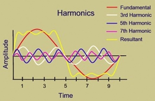
A distorted wave may look messy, but it is not random. If that pattern repeats, it can be separated into a group of sine waves stacked together. One is the normal fundamental wave. The others sit at higher frequencies.
A repeating distorted waveform can contain a clean 60 Hz base wave plus smaller waves at 180 Hz, 300 Hz, 420 Hz, and higher multiples. Those added layers are harmonics.
Fourier analysis made easy
The usual tool for this is Fourier analysis. You do not need the math to grasp the idea. Fourier analysis takes a waveform that looks tangled and shows the individual frequency pieces inside it.
That matters because looking at the raw wave alone does not tell you how strong each harmonic component is. Once you decompose the wave, you can see which harmonic orders are present and how large they are.
H1, H3, H5, and other harmonic orders
Engineers label the main wave as H1, or the first harmonic. That sounds odd, but it simply means the normal fundamental component. The trouble starts with H3, H5, H7, and higher orders.
Here is the quick picture for a 60 Hz system:
| Harmonic order | Frequency |
|---|---|
| H1 | 60 Hz |
| H3 | 180 Hz |
| H5 | 300 Hz |
| H7 | 420 Hz |
In a 50 Hz system, the same idea applies. H3 becomes 150 Hz, and H5 becomes 250 Hz. The pattern is simple: harmonic order multiplied by the fundamental frequency.
Why repeating patterns matter more than one-time spikes
Not every ugly waveform is a harmonic problem. Harmonics are steady-state, repeating distortions. They appear cycle after cycle, or at least stay present long enough to act like a continuing condition.
A sudden one-time spike is different. That is a transient. It may be serious, but it is not the same thing. Harmonics repeat. Transients flash and fade.
A simple circuit example that shows how harmonics change power
A textbook example makes this much easier to see. Start with a 1,000 V AC source at 60 Hz feeding a 10 ohm resistor. In a plain resistive circuit, current and voltage stay in step. The power is 100 kW, and the current is 100 A.
Now place a synchronous switch in series with the resistor and control it so current flows only for part of each half-cycle. The source voltage is still a sine wave, but the current is no longer smooth. It turns into pulses.
What happens when current flows in pulses
Because the switch blocks current for part of the cycle, the resistor no longer sees a normal sinusoidal current. Average power drops, in this example, to 50 kW. The RMS current also changes, landing at about 70.7 A.
That already tells you something important. The source frequency never changed. The generator still runs at 60 Hz. Yet the load-side current has a new shape because a nonlinear element interrupted the flow in a repeating way.
Why power factor drops even in a resistive circuit
After Fourier analysis, the chopped current can be split into a 60 Hz fundamental component plus harmonic components at higher frequencies. In the example, the 60 Hz current component is about 59.3 A RMS and appears to lag the voltage by about 32.5 degrees.
That is the surprise. A plain resistor should not create a lagging current on its own. Yet the distorted waveform changes the apparent relationship between voltage and current.
As a result, the power factor drops to about 84.3 percent. Apparent power rises to about 59.3 kVA, even though the active power is only 50 kW. Harmonics changed the behavior of the circuit without adding a classic inductor or capacitor.
Where the extra heating and hidden power go
The example also shows why harmonics are more than a drawing on paper. Part of the power is no longer doing clean useful work at the fundamental frequency. Some of it turns into distortion power that still heats equipment.
In the same example, the resistor absorbs about 35.2 kW from the fundamental component. The remaining 14.8 kW appears as harmonic power and ends up as extra heating stress in the circuit. That is why harmonic currents can make a simple system run hotter than expected.
This is also why sites with heavy electronic loads often chase heat problems before they even identify harmonics as the root cause.
The real costs of harmonics in day-to-day operation
Harmonics show up in bills, maintenance calls, and unexplained failures. They do not always cause dramatic breakdowns on day one. More often, they shorten margins until normal equipment starts behaving badly.
This power quality and harmonics overview points to the same pattern: overheating, protective device misoperation, and stress on connected equipment.
Overheating, losses, and shorter equipment life
Distorted current raises losses in cables, transformers, and motors. Heat builds faster because the system is carrying current that is not helping the load in a clean way.
That extra heat attacks insulation and shortens equipment life. It can also show up inside drives. In VFD systems, capacitor stress is one piece of that picture, and this look at why VFD capacitors burn out connects poor operating conditions with early component failure.
Poor power factor, penalties, and wasted capacity
A site with significant harmonics can show a lower overall power factor, even when the problem is not classic inductive load alone. That matters because low power factor can lead to utility penalties and poor use of installed capacity.
More current has to move through the same wires and equipment to deliver the same useful power. That means less room for productive load and more strain on the system you already paid for.
Trips, glitches, and trouble for sensitive electronics
Protective devices do not always love distorted current. Breakers may nuisance trip. Sensitive electronics may misbehave. Communication circuits can also pick up interference in some settings.
Neutral conductors deserve special attention. In systems with strong triplen harmonics, harmonic currents can pile up in the neutral rather than cancel out. If the neutral is undersized, it can overheat and fail.
Triplen harmonics, interharmonics, and the patterns engineers watch for
Some harmonic types deserve more attention because they create special trouble. Two of the most common terms are triplen harmonics and interharmonics.
Why triplen harmonics deserve extra attention
Triplen harmonics are the odd multiples of the third harmonic: 3rd, 9th, 15th, 21st, and so on. These components are a frequent concern in three-phase systems.
They matter because they can add together in the neutral conductor. Instead of canceling, they stack. That can overheat the neutral and create a problem that is easy to miss if you only think about phase currents.
What makes interharmonics different
Interharmonics are frequency components that do not land exactly on whole-number multiples of the fundamental. You might see values tied to 1.5, 2.3, or 3.5 times the fundamental frequency.
They are less common in many everyday power systems, but they still matter when they appear. Because they do not line up neatly with normal harmonic orders, they can be harder to spot and analyze.
How to spot harmonics and start reducing them
You cannot remove harmonics from modern power systems in a perfect way. Too many useful loads create them by nature. Still, you can measure them, reduce them, and keep them within reasonable limits.
The first step is often noticing the pattern. Harmonic problems rarely announce themselves with a label.
Signs that harmonics may already be in the system
A site may have harmonic trouble if you keep seeing symptoms like these:
- Transformers, cables, or neutrals run hotter than expected.
- Breakers or protective devices trip without a clear overload.
- Drives, UPS units, or electronic equipment act erratically.
- Efficiency drops, yet the load profile does not explain it.
- Power factor stays poor even after basic correction efforts.
If several of those signs appear together, power quality testing is worth serious attention.
Common ways to reduce the problem
Mitigation starts with understanding the source. If VFDs are a major contributor, drive-side solutions often help. This guide on why use line reactors with VFDs shows one common method for limiting harmonic current and improving upstream conditions.
Other common approaches include passive filters, active filters, better drive selection, proper transformer sizing, and thoughtful load planning. In three-phase systems, neutral sizing also matters where triplen harmonics are present. The goal is not perfection. The goal is a system that runs cool, stable, and predictable.
What to remember about harmonics
The same hidden issue can start in a phone charger and grow into a plant-wide headache when enough nonlinear loads gather on one system. Harmonics are repeating distortions tied to the main power frequency, and they can change how a circuit behaves, how much heat it produces, and how much useful power it delivers.
Once you understand the path from pulsed current to distorted wave, the symptoms make more sense. Hot equipment, poor power factor, false trips, stressed neutrals, and shorter equipment life are all part of the same story.
The good news is that harmonics are not guesswork. They can be identified, measured, and reduced, which turns a vague power quality problem into something you can manage with clear engineering decisions.