A control schematic can look like a maze when you first open a switchgear or circuit breaker drawing. Lines cross the page, contacts appear far from their coils, and a single circuit may disappear onto another sheet without warning.
Electrical schematics become much easier when you read them in a fixed order. Start with the devices, learn the drawing language, confirm the assumed states, follow the supply path, and then trace every cross-reference.
That method won’t replace hands-on practice or safe work procedures, but it gives every new drawing a clear place to begin.
Table of Contents
Electrical Schematics Are the Map of a Control Circuit
A physical panel shows where wires and devices sit inside a cabinet. A schematic shows how those devices work together. It maps the control logic, switching paths, protective devices, feedback signals, and electrical interlocks that determine whether a command can reach a coil or load.
This matters in low-voltage and medium-voltage switchgear, ring main units, high-voltage circuit breakers, control panels, PLC systems, and industrial automation. A circuit may include a local push button, a remote command, a protective relay contact, a breaker auxiliary contact, and a closing coil. The schematic puts that logic into a readable sequence, even when those parts sit in different places physically.
Conventions can differ by country, manufacturer, project, and drafting software. For example, IEC 60617 graphical-symbol references provide common diagram symbols, but the legend in the drawing set should always guide your interpretation.
Build the Foundation Before You Trace a Circuit
Don’t begin by following random wires across the page. First, identify the equipment and understand what each device does when power reaches it.
Learn What the Devices Do
Contactors, relays, fuses, push buttons, selector switches, terminal blocks, indicator lamps, and auxiliary contacts each have a job in the control circuit. A fuse protects the circuit. A push button creates a momentary command. A selector switch may choose local or remote control.
A contactor is a useful starting example. Its coil energizes when the correct supply path is complete. That action changes the state of its normally open and normally closed auxiliary contacts. If you don’t understand that physical action, a symbol on paper has little meaning.
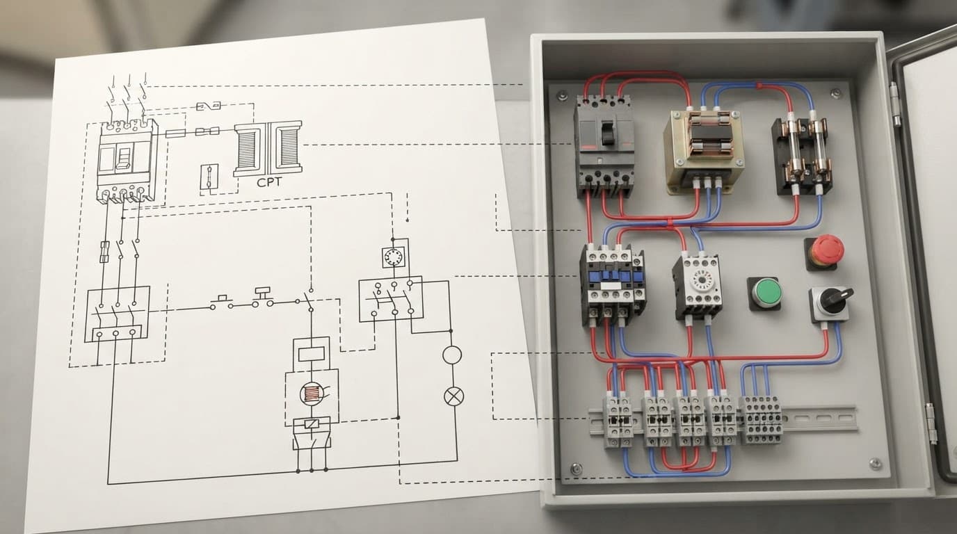
Read the Title Block and Legend First
The title block tells you what you are looking at. It may identify a breaker closing circuit, trip circuit, auxiliary supply, PLC wiring page, project name, revision, drawing number, voltage, and page number.
Next, find the legend, abbreviation list, or bill of materials. The project documentation explains symbols and references that may not match another manufacturer’s drawings. A comparison of NEMA and IEC wiring symbols also shows why assumptions based on a familiar drawing style can cause mistakes.
Decode References Such as K1, K2, A1, and A2
Device designations connect related parts across the drawing. K1 may identify a contactor or relay, while K2 identifies another device of the same type. A contactor coil and all of its auxiliary contacts can carry the same K1 reference, even when they appear on separate pages.
A1 and A2 commonly identify the terminals of a contactor or relay coil. Still, confirm the project’s designation rules before tracing the circuit.
Check the Assumptions Before Reading Contact States
A contact that appears open or closed only makes sense when you know the condition assumed by the designer. Most control drawings show relays and contactors in their de-energized state, but the notes must confirm it.
Read NO and NC Contacts in Their Default Condition
In a de-energized state, a normally open contact is open and a normally closed contact is closed. When the associated coil energizes, those contacts change state. The same principle applies to breaker auxiliary contacts, limit switches, disconnect switches, and mechanical interlocks.
A contact symbol is a snapshot of an assumed equipment state, not proof of its live condition in the field.
Look for notes at the top or bottom of pages, or in the general notes section. A circuit breaker drawing may state whether the breaker is shown open or closed. Without that note, you can follow a correct wire path and still draw the wrong conclusion.
Follow the Intended Power Direction
Many DC control schematics place the positive rail at the top and the negative rail at the bottom. Read downward: positive supply, fuse or protective device, permissive contacts, coil or load, then the negative return. DC control power in switchgear circuits is common because breaker controls, relays, indication, and trip circuits need a dependable auxiliary supply.
AC drawings often flow from left to right, starting at the source and moving toward the load or return. Identify the phase, neutral, protective earth, control transformer, and voltage labels before assuming two nearby lines belong to the same circuit.
Trace Power Across Pages Without Guessing
Large drawings cannot fit every logic path on one sheet. That is why power rails, control wires, and signals often continue from one page to another.
Use Page and Column References
A reference such as 3.10 commonly means the circuit continues from page 3, column 10. Find page 3, locate column 10 at the top of the drawing, and confirm the matching wire, voltage, symbol, or busbar.
These markers work like a map grid. They may identify an incoming supply, an outgoing control wire, a continuation of a DC bus, or a feedback signal. Never treat a continuation mark as a guessed connection. Verify both ends.
Trace One Operation All the Way Through
For a breaker close circuit, begin at the control supply. Follow the path through the fuse, permissive contacts, local or remote selector switch, close push button or remote command, and finally the closing coil. Then find the auxiliary contacts that provide indication, seal-in logic, or blocking conditions.
Mark each confirmed path as you go. When a command fails, record every contact that must close for the coil to energize. This prevents the common mistake of staring at one page while the actual interruption sits on another.
Keep a Short Troubleshooting Sequence
Use this order when studying or fault-finding:
- Identify the circuit’s purpose and its control voltage.
- Read the title block, notes, legend, and device references.
- Confirm the default state of contacts and equipment.
- Find the supply, then follow the intended power direction.
- Check every page reference, terminal number, wire number, auxiliary contact, and interlock.
Electrical CAD tools can produce terminal plans, wire lists, device lists, and bills of materials. However, documentation only helps when you can read the logic behind it. Live testing and cabinet work also require proper training, isolation, lockout procedures, and appropriate personal protective equipment.
A Repeatable Way to Read Complex Drawings
Reading electrical schematics is a disciplined process, not a test of how many symbols you can recognize at a glance. Start with the devices, learn the project’s symbols and references, confirm the assumed states, follow the power path, and connect each continuation across the drawing set.
Begin with one simple control circuit and trace it by hand. With repeated practice, the lines that first looked like a maze begin to show a clear, testable chain of logic.