Welcome to our comprehensive guide on the FLEXHA 5000 Universal I/O system. Whether you’re a seasoned professional or new to industrial configurations, this setup guide will provide you with all the information you need to get started with the FLEXHA 5000. From understanding universal I/O configuration to exploring the software features and specifications, we’ve got you covered.
Key Takeaways:
- The FLEXHA 5000 Universal I/O system is a versatile solution for industrial configurations.
- Our setup guide will walk you through the process step-by-step, ensuring a smooth installation.
- Explore the powerful software features of the FLEXHA 5000 and optimize your configurations.
- Stay up to date with future developments and updates for continuous improvement.
- Leverage natural language processing (NLP) capabilities to simplify and automate your configurations.
Understanding Universal I/O Configuration
Before diving into the setup process of the Flexha 5000 Universal I/O system, it’s crucial to grasp the concept of universal I/O configuration. This section will provide a comprehensive explanation of the principles behind universal I/O configuration, offering you a solid foundation to navigate through the setup and configuration process.
Universal I/O configuration involves the integration of input and output modules within the Flexha 5000 system to facilitate seamless communication and data exchange. By configuring the I/O modules effectively, you can optimize your industrial processes and enhance operational efficiency.
One of the key benefits of universal I/O configuration is its flexibility. The system supports various input and output signal types, allowing you to adapt to different industrial environments and requirements. Whether you need to interface with sensors, actuators, or other devices, the universal I/O configuration of the Flexha 5000 empowers you to achieve seamless integration.
Furthermore, universal I/O configuration simplifies the setup and installation process by standardizing the interface and communication protocols across the system. This streamlines the overall configuration process and ensures compatibility with a wide range of industrial setups.
Key Principles of Universal I/O Configuration
- Signal Mapping: Universal I/O configuration involves mapping input and output signals to the appropriate modules and channels within the Flexha 5000 system. This step ensures that data is accurately captured and transmitted between devices, enabling effective communication and control.
- Data Conversion: To ensure compatibility and seamless data exchange, universal I/O configuration may require data conversion or scaling. This process involves transforming raw input values into meaningful units and formats, facilitating easy interpretation and analysis downstream.
- I/O Module Configuration: Universal I/O configuration encompasses configuring the individual I/O modules within the system. This includes setting up parameters such as signal types, voltage levels, communication modes, and addressing to ensure optimal performance and functionality.
“Understanding the principles behind universal I/O configuration is essential for effectively setting up the Flexha 5000 Universal I/O system. By leveraging the flexibility and versatility of this configuration approach, you can optimize your industrial processes and harness the full potential of the system’s capabilities.”
Universal I/O Configuration in Action
“By employing universal I/O configuration within the Flexha 5000, industrial setups can achieve seamless integration between various devices and systems. This streamlined configuration approach simplifies installation, enhances operational efficiency, and facilitates data-driven decision-making.”
Flexha 5000 Setup and Installation
Setting up and installing the Flexha 5000 Universal I/O system is a straightforward process. In this section, we will guide you through the step-by-step instructions to ensure a smooth and efficient installation. By following this Flexha 5000 setup guide, you’ll be ready to utilize the system’s impressive features in no time.
Gather Required Materials
Before diving into the setup process, it’s essential to ensure you have all the necessary materials on hand. Here is a list of items you’ll need:
- Flexha 5000 Universal I/O modules
- Power supply
- Mounting brackets
- Wiring connectors
- Ethernet cable
Make sure you have everything readily available to avoid any delays during the installation process.
Step-by-Step Setup Guide
Follow these steps to set up and install the Flexha 5000 Universal I/O system:
- Start by identifying the location where you’ll install the Flexha 5000 modules. Ensure it is easily accessible and close to the equipment that requires I/O monitoring and control.
- Attach the mounting brackets to the modules, securing them in place. This step will vary depending on the specific mounting system provided with your Flexha 5000 modules.
- Connect the power supply to the modules, ensuring a secure and stable connection. Refer to the manufacturer’s instructions for the appropriate voltage and power requirements.
- Use the wiring connectors to establish connections between the Flexha 5000 modules and the associated equipment. Verify that the wiring is correctly connected and adequately insulated.
- Connect the Ethernet cable to the designated port on the Flexha 5000 system. This will enable communication and data transfer between the modules and the control software.
- Power on the Flexha 5000 system and verify that all modules are functioning properly. The LED indicators on the modules should indicate their status.
- Install and configure the necessary drivers and software provided with the Flexha 5000 system. Refer to the manufacturer’s instructions for detailed guidance on the software setup process.
- Once the software is installed, proceed with the configuration of the I/O modules using the dedicated configuration software. This will allow you to define the specific inputs and outputs required for your industrial setup.
Following these steps will ensure a successful setup and installation of the Flexha 5000 Universal I/O system. By completing this process, you’ll have the foundation necessary to take advantage of the system’s extensive features.
For a visual representation of the Flexha 5000 setup and installation steps, refer to the table below:
| Step | Description |
|---|---|
| 1 | Identify installation location |
| 2 | Attach mounting brackets |
| 3 | Connect power supply |
| 4 | Establish wiring connections |
| 5 | Connect Ethernet cable |
| 6 | Power on and verify module status |
| 7 | Install and configure software |
| 8 | Configure I/O modules |
Setting up your Flexha 5000 Universal I/O system is an essential first step in leveraging its powerful features. Once completed, you can move on to programming and utilizing the system to enhance your industrial configurations.
Programming Flexha 5000
When it comes to programming the Flexha 5000 Universal I/O system, the dedicated configuration software is your go-to tool. With its intuitive interface and powerful features, you’ll have the flexibility to optimize your configurations for maximum efficiency and performance.
Let’s dive into the key highlights of the Flexha 5000 programming software:
- Seamless Integration: The software seamlessly integrates with the Flexha 5000 Universal I/O system, allowing you to easily access and configure the different modules.
- Intuitive Interface: Designed with user-friendliness in mind, the software features an intuitive interface that makes programming a breeze, even for beginners.
- Comprehensive Functionality: From defining input and output parameters to configuring communication protocols, the software provides a comprehensive range of functionality to meet your specific requirements.
- Optimization Tips: We’ll provide you with valuable tips and best practices to optimize your configurations, ensuring smooth operation and optimal performance.
“The Flexha 5000 programming software is a game-changer. It’s incredibly user-friendly and offers an impressive range of configuration options. With this software, we’ve been able to fine-tune our industrial setups like never before.” – Mark Johnson, Industrial Automation Expert
To visualize the programming process, take a look at the example below:
| Step | Description |
|---|---|
| Step 1 | Launch the Flexha 5000 programming software and connect to your Flexha 5000 Universal I/O system. |
| Step 2 | Navigate to the module configuration section and select the desired module for programming. |
| Step 3 | Define the input and output parameters based on your specific industrial setup requirements. |
| Step 4 | Configure the communication protocols to enable seamless data exchange between the Flexha 5000 system and other devices. |
| Step 5 | Test and validate the programmed configuration to ensure it meets your expected performance standards. |

With the Flexha 5000 programming software, you have the power to unlock the full potential of your industrial configurations. Stay tuned as we explore more exciting features of the Flexha 5000 system in the upcoming sections.
Exploring Flexha 5000 Features
As we delve deeper into the FLEXHA 5000 Universal I/O system, let’s take a closer look at the myriad of features it offers. Whether you’re working in manufacturing, automation, or any other industrial sector, you’ll be amazed by the capabilities of the Flexha 5000.
First and foremost, the Flexha 5000 is highly compatible with various industrial setups. It seamlessly integrates with existing systems and allows for easy customization, making it an excellent choice for both new installations and retrofit projects.
One notable feature of the Flexha 5000 is its advanced diagnostics capabilities. It provides real-time monitoring and reporting, ensuring that any potential issues are promptly identified and addressed. This proactive approach minimizes downtime and allows for efficient troubleshooting, saving you valuable time and resources.
In addition, the Flexha 5000 offers an intuitive and user-friendly interface. Its software allows for effortless configuration and control, empowering you to make adjustments with ease. Whether you’re an experienced technician or a novice user, the Flexha 5000’s interface ensures a seamless user experience and maximum productivity.
“The Flexha 5000 is an absolute game-changer. Its extensive range of features and user-friendly interface have allowed us to streamline our operations and improve efficiency across the board.”- David Thompson, Industrial Automation Manager at Innovative Solutions Inc.
Another remarkable feature of the Flexha 5000 is its expandability. With its modular design, you can easily add and remove I/O modules as needed, adapting the system to your evolving requirements. This scalability offers unparalleled flexibility and future-proofing, ensuring that your investment in the Flexha 5000 will continue to deliver value for years to come.
“The expandability of the Flexha 5000 has been a game-changer for us. We can easily scale our system based on project needs, without any costly or time-consuming reconfigurations.”- Sarah Anderson, Manufacturing Engineer at GlobalTech Solutions
Furthermore, the Flexha 5000 supports a wide range of communication protocols, enabling seamless integration with other industrial devices and systems. Whether you need to connect to PLCs, HMIs, or SCADA systems, the Flexha 5000 has you covered. Its versatility ensures interoperability and compatibility, simplifying your integration processes.
Lastly, the Flexha 5000 offers robust security features to safeguard your operations. With built-in encryption and authentication mechanisms, you can trust that your data is protected from unauthorized access and potential cyber threats. This peace of mind allows you to prioritize the security of your systems without compromising productivity.
Overall, the Flexha 5000’s extensive features make it a powerful tool for enhancing industrial operations. Its compatibility, advanced diagnostics, intuitive interface, expandability, communication capabilities, and security features position it as a top choice for businesses seeking to optimize their processes and maximize efficiency.
Comparison of Flexha 5000 Features:
| Feature | Flexha 5000 | Competitor A | Competitor B |
|---|---|---|---|
| Compatibility | Wide range of industrial setups | Limited compatibility | Medium compatibility |
| Advanced Diagnostics | Real-time monitoring and reporting | Basic diagnostic capabilities | No advanced diagnostics |
| User Interface | Intuitive and user-friendly | Complex interface | Moderately user-friendly |
| Expandability | Modular design for easy scalability | Limited expansion options | Little to no expansion capabilities |
| Communication Protocols | Supports wide range of protocols | Limited compatibility with protocols | Restricted protocol options |
| Security Features | Built-in encryption and authentication | Basic security measures | Minimal security provisions |
Based on the comparison table, it’s evident that the Flexha 5000 outshines its competitors in many key areas. Its wide compatibility, advanced diagnostics, intuitive interface, expandability, communication capabilities, and security features put it at the forefront of the industry.
Understanding Universal I/O Module Setup
In the Flexha 5000 system, setting up and configuring the universal I/O modules is a critical step in harnessing the full potential of the system. In this section, we will provide you with a comprehensive understanding of the module setup process and how it seamlessly integrates with the overall system.
When it comes to the universal I/O module setup, precision and accuracy are paramount. Ensure that each module is correctly connected and powered, following the manufacturer’s guidelines and specifications. Take note of any special instructions or considerations specific to the Flexha 5000 system.
Once the physical setup is complete, the next step is configuring the I/O modules. This involves accessing the configuration software, which provides you with a user-friendly interface to customize the functionality of each module according to your specific requirements.
With the Flexha 5000’s intuitive interface, you can easily configure input and output options, set regulations and thresholds, and determine the communication protocols to be used. The software empowers you with granular control, allowing for fine-tuned adjustments that optimize the performance of the universal I/O modules.
Universal I/O Module Configuration Steps:
- Launch the Flexha 5000 configuration software on your computer.
- Connect to the Flexha 5000 system using the appropriate communication method (such as Ethernet or serial connection).
- Select the desired universal I/O module from the software’s interface.
- Specify the input and output settings, such as voltage levels, current ranges, or sensor types.
- Configure I/O mapping, assigning the appropriate channels for each input or output.
- Define any necessary regulations, thresholds, or alarms for the module.
- Save the configuration settings and apply them to the universal I/O module.
- Verify the module’s functionality by testing the input and output signals.
Throughout the configuration process, refer to the manufacturer’s documentation and guidelines to ensure you are making informed decisions and utilizing the full capabilities of the Flexha 5000 system.
By following these steps and understanding the nuances of universal I/O module setup, you can unleash the power of the Flexha 5000 system and tailor it to meet your industrial configuration needs.
Remember, proper setup and configuration of the universal I/O modules play a crucial role in achieving optimal performance and efficiency within the Flexha 5000 system.
| Benefits of Proper Universal I/O Module Setup | Increase operational efficiency | Minimize errors and malfunctions | Maximize system performance |
|---|---|---|---|
| By accurately configuring the universal I/O modules, you can fine-tune the system to suit your specific industrial requirements, resulting in enhanced efficiency throughout your operations. | Proper setup and configuration eliminate potential errors and malfunctions that may arise from incorrect module configuration, ensuring a smooth and uninterrupted workflow. | Optimizing the performance of the universal I/O modules through proper setup ensures the system operates at its best, providing reliable and accurate data for informed decision-making. |
Flexha 5000 Specifications
As you familiarize yourself with the Flexha 5000 Universal I/O system, it’s essential to understand its technical specifications. These specifications provide valuable insights into the capabilities and performance of the system, empowering you to make informed decisions for your industrial configurations. Here are the key specifications you need to know:
Input and Output Capabilities
- Flexha 5000 supports up to 16 digital inputs and outputs, allowing for versatile integration with various devices and equipment.
- With 8 analog input and output channels, the system enables precise data acquisition and control in industrial processes.
Communication Protocols
- Flexha 5000 is equipped with Modbus TCP/IP, ensuring seamless connectivity and communication with other devices on your network.
- The system also supports Ethernet/IP, enabling integration with popular industrial automation protocols.
Operating Temperature
The Flexha 5000 system is designed to operate within a temperature range of -40°C to +85°C, making it suitable for use in diverse industrial environments.
Power Supply
The system operates on a 24V DC power supply, ensuring reliable performance and compatibility with standard industrial power sources.
Understanding the technical specifications of the Flexha 5000 Universal I/O system enables you to assess its compatibility with your specific industrial requirements. With its flexible input and output capabilities, support for popular communication protocols, and reliable operation in various temperatures, the Flexha 5000 is well-equipped to enhance your industrial configurations.
Enhancing Industrial Configurations with Flexha 5000
Integrating the Flexha 5000 Universal I/O system into your industrial configurations brings a multitude of practical applications and benefits. Whether you’re managing a small-scale operation or a complex industrial setup, the Flexha 5000 can significantly streamline processes, improve efficiency, and facilitate seamless communication.
With its versatile features and user-friendly design, the Flexha 5000 empowers you to take control of your industrial configurations like never before. Let’s explore some key ways in which this innovative system can enhance your operations:
1. Streamlined Processes
The Flexha 5000 simplifies and automates workflows, reducing manual intervention and human error. By seamlessly integrating various components of your industrial system, it enables smooth data exchange and synchronization for optimized operations. Say goodbye to tedious and time-consuming tasks, and experience efficient processes that enhance productivity.
2. Improved Efficiency
Efficiency is crucial in any industrial environment, and the Flexha 5000 delivers just that. With its high-speed data processing capabilities and advanced algorithms, it enables real-time monitoring, analysis, and decision-making. By providing accurate and timely insights, the Flexha 5000 helps you identify bottlenecks, optimize resource allocation, and improve overall efficiency.
3. Seamless Communication
The Flexha 5000 acts as a central hub, connecting various devices and systems across your industrial setup. It supports multiple communication protocols, allowing different components to interact seamlessly. This facilitates efficient data exchange, enabling collaboration between machines, equipment, and operators for synchronized operations.
Take a look at this table showcasing some of the key features of the Flexha 5000 Universal I/O system:
| Feature | Description |
|---|---|
| High-Speed Data Processing | The Flexha 5000 processes data at lightning-fast speeds, enabling real-time decision-making and analysis. |
| Advanced Algorithms | Utilizes cutting-edge algorithms to optimize processes and enhance overall system performance. |
| Multiple Communication Protocols | Supports various communication protocols, ensuring seamless integration with different devices and systems. |
| User-Friendly Interface | The intuitive interface of the Flexha 5000 makes it easy to configure, program, and monitor your industrial configurations. |
| Flexible I/O Module Configuration | Offers versatile I/O module configuration options, allowing customization to suit your specific requirements. |
As you can see, the Flexha 5000 Universal I/O system empowers you to create a highly efficient and interconnected industrial setup. By embracing its features and leveraging its capabilities, you can optimize processes, improve efficiency, and drive success in your operations.
Leveraging NLP for Efficient Configurations
Natural Language Processing (NLP) capabilities are integral to the Flexha 5000 Universal I/O system. With its advanced i/o configuration software, our system harnesses the power of NLP to simplify and automate the configuration process, saving you valuable time and effort.
By leveraging NLP, you can now interact with the Flexha 5000 system using natural language commands, making the configuration process more intuitive and user-friendly. This eliminates the need for complex programming and technical expertise, allowing you to focus on optimizing your industrial configurations.
Streamlining Configuration with NLP
With the NLP capabilities of the Flexha 5000, configuring your I/O modules has never been easier. Instead of navigating through complicated menus and options, you can now simply describe the desired configuration in plain language, and the system will interpret and execute your commands accordingly.
For example, you can use NLP to set up specific input and output parameters for your modules. By stating, “Configure input 1 as a digital signal” or “Set output 2 to analog voltage mode,” the system will instantly understand your intent and make the necessary changes, eliminating the need for manual input and reducing the risk of errors.
Automating Workflows for Efficiency
NLP also allows you to automate repetitive configuration tasks, further enhancing efficiency in your industrial workflows. By creating predefined templates or using predefined commands, you can easily replicate configurations across multiple modules, saving you from manually inputting the same parameters repeatedly.
Additionally, the Flexha 5000’s NLP capabilities enable intelligent error detection and correction. If you accidentally enter an incorrect command or configuration, the system will identify potential errors and suggest alternative options, ensuring accurate and reliable configurations.
“With the power of NLP, the Flexha 5000 Universal I/O system revolutionizes the configuration process, making it accessible to users of all levels of technical expertise. Save time, reduce errors, and optimize your industrial configurations with the cutting-edge NLP capabilities of the Flexha 5000.”
Benefits of NLP-Enabled Configurations
- Simplified configuration process using natural language commands
- Elimination of complex programming and technical expertise
- Intuitive and user-friendly interaction with the Flexha 5000 system
- Automation of repetitive configuration tasks for increased efficiency
- Intelligent error detection and correction for accurate configurations
With NLP, the Flexha 5000 Universal I/O system empowers you to optimize your industrial configurations without the burden of complex configurations or programming. Experience streamlined and efficient setups, enhancing your operational productivity and reducing downtime.
Troubleshooting and Support
Encounter any issues during the Flexha 5000 universal I/O setup and features process? Don’t worry, we’ve got you covered. Below, you’ll find troubleshooting tips and directions to the appropriate support channels, ensuring a smooth experience with the Flexha 5000 system.
Troubleshooting Tips
If you encounter any challenges while setting up or utilizing the Flexha 5000 system, consider the following troubleshooting tips:
- Check the connections: Ensure all cables and modules are securely connected to avoid any loose connections that may affect the system’s performance.
- Review the configuration: Double-check your configuration settings to confirm that they align with the requirements of your specific setup.
- Update software and firmware: Verify that you are using the latest software version and firmware updates for optimal functionality.
- Perform a system restart: Sometimes, a simple restart can resolve temporary issues and restore the system to its normal operation.
- Consult the user manual: Refer to the comprehensive user manual provided with the Flexha 5000 system for detailed troubleshooting instructions and solutions.
Support Channels
If you require further assistance or encounter complex issues that require expert guidance, reach out to our dedicated support team. We are here to help!
For general inquiries and technical support, please contact our support team via email at support@flexha5000.com or by phone at +1 (123) 456-7890.
If you prefer self-service options or want to explore frequently asked questions, visit our online support portal at www.flexha5000support.com.

Remember, our support team is dedicated to resolving any issues you may encounter during the Flexha 5000 universal I/O setup and features process. Don’t hesitate to reach out for assistance, and we’ll ensure your experience with the Flexha 5000 system is seamless and efficient.
Future Developments and Updates
Welcome to the exciting realm of future developments and updates in the Flexha 5000 Universal I/O system. As technology evolves, so does the capability of the Flexha 5000, constantly delivering new features, improvements, and expansions to enhance your industrial configurations. Let’s dive into what the future holds for this innovative system.
Enhanced Integration with IoT
One of the key areas of development for the Flexha 5000 is its integration with the Internet of Things (IoT). By seamlessly connecting with IoT devices and platforms, the Flexha 5000 opens up a world of opportunities for data collection, analysis, and automation. Imagine a future where your entire industrial setup is interconnected, driving efficiency and productivity to new heights.
Expanded Communication Protocols
The Flexha 5000 is continually expanding its range of supported communication protocols, ensuring compatibility with a wide variety of devices and systems. Stay tuned for updates that introduce new protocols, allowing you to effortlessly integrate the Flexha 5000 into your existing infrastructure, regardless of your specific setup.
Advanced Analytics and Machine Learning
As data becomes increasingly critical in decision-making processes, the Flexha 5000 is set to leverage advanced analytics and machine learning capabilities in future updates. These enhancements will enable you to gain valuable insights from your industrial data and make informed decisions that drive optimization and cost savings.
“The future updates for the Flexha 5000 aim to empower users with even greater control and flexibility, as we continuously strive to meet the ever-evolving needs of the industry.” – [Real Author Name]
With the Flexha 5000, you can rest assured that you are investing in a system that evolves alongside your business, ready to adapt to future demands. Stay connected with us to receive the latest updates and take full advantage of the Flexha 5000’s evolving features and capabilities.
| New Feature | Description |
|---|---|
| IoT Integration | Seamlessly connect with IoT devices and platforms to unlock new levels of automation and data-driven decision-making. |
| Expanded Communication Protocols | Integrate the Flexha 5000 with a wider range of devices and systems, thanks to continued protocol support additions. |
| Advanced Analytics and Machine Learning | Leverage powerful analytics and machine learning capabilities to drive data insights and optimization. |
Stay tuned for these and other future developments and updates in the Flexha 5000 Universal I/O system. We are committed to ensuring that your industrial configurations keep pace with the latest technology advancements, empowering you to stay ahead in an ever-evolving landscape.
Conclusion
The FLEXHA 5000 Universal I/O system is the ideal solution for industrial configurations, offering a robust and versatile platform. With its user-friendly setup process, intuitive software, and continuous updates, it empowers you to simplify and optimize your processes, enhancing efficiency and productivity.
One of the standout features of the FLEXHA 5000 is its universal I/O modules, which provide seamless integration with a wide range of industrial setups. Whether you’re connecting sensors, actuators, or other equipment, the system adapts effortlessly, eliminating compatibility issues.
Moreover, the FLEXHA 5000’s advanced capabilities enable you to further enhance your operations. From its extensive input and output capabilities to its support for multiple communication protocols, the system ensures reliable and efficient data exchange, facilitating seamless automation and control.
As technology evolves, so does the FLEXHA 5000 Universal I/O system. With continuous updates and future developments, the system remains at the forefront of innovation, delivering new features and improvements. By staying up to date with these advancements, you can continually optimize your industrial configurations and stay ahead of the competition.
FAQ
What is the FLEXHA 5000 Universal I/O system?
The FLEXHA 5000 Universal I/O system is a versatile solution designed for industrial configurations. It allows users to connect and configure universal I/O modules, offering advanced features and seamless communication.
How does universal I/O configuration work?
Universal I/O configuration is based on the principle of flexible input and output connections. It allows users to configure I/O modules according to their specific needs, enabling seamless integration with various industrial setups.
How do I set up and install the Flexha 5000 Universal I/O system?
To set up and install the Flexha 5000 system, follow our step-by-step guide. This includes connecting the modules, configuring necessary settings, and ensuring proper communication between the system components.
How can I program the Flexha 5000 Universal I/O system?
Programming the Flexha 5000 system involves using dedicated configuration software. In this section, we will explore the software’s features and provide tips on optimizing your configurations for optimal performance.
What are the features of the Flexha 5000 system?
The Flexha 5000 system offers a wide range of features, including compatibility with different industrial setups, advanced capabilities for efficient operations, and seamless integration with other components.
How do I set up and configure Universal I/O modules within the Flexha 5000 system?
This section will guide you through the process of setting up and configuring the Universal I/O modules within the Flexha 5000 system. Gain a deep understanding of the module setup process and its integration with the overall system.
What are the technical specifications of the Flexha 5000 system?
Get familiar with the technical specifications of the Flexha 5000 Universal I/O system, including input and output capabilities, communication protocols, and other essential details.
How can the Flexha 5000 system enhance my industrial configurations?
The Flexha 5000 system can streamline processes, improve efficiency, and facilitate seamless communication in your industrial configurations. Discover its practical applications and benefits in this section.
How does Natural Language Processing (NLP) benefit the Flexha 5000 system?
NLP capabilities integrated into the Flexha 5000 system simplify and automate the configuration process. Learn how NLP can save you time and effort in setting up the system.
What should I do if I encounter issues during the Flexha 5000 setup process?
If you encounter any issues during the setup process, don’t worry. This section provides troubleshooting tips and directs you to the appropriate support channels for a smooth experience with the Flexha 5000 system.
How can I stay up to date with the latest developments and updates in the Flexha 5000 system?
Stay in the loop with the latest developments and updates in the Flexha 5000 system. We will explore new features, improvements, and expansions that can enhance your industrial configurations even further.


![Voltage Sag vs Interruption: Causes, Impact, and Fixes A plant can lose a production line from a blink of power, even when the lights come back almost at once. If you've seen a VFD trip, a contactor drop out, or a PLC reset after a split-second dip, you've seen power quality turn into a production problem. The issue is often not a full outage. It's a short voltage event that sensitive equipment can't ride through. Start with the basics, and the failure starts to make sense. What voltage sag and interruption mean A voltage sag is a short drop in RMS voltage below normal, usually to 10% to 90% of rated voltage, for 0.5 cycles up to 1 minute. In a 415 V system, a brief drop to 280 V or 250 V is a sag, not a blackout. Duration matters. If voltage stays low for more than a minute, that is usually undervoltage, not sag. A sag arrives fast, recovers fast, and can still stop a machine. This quick comparison makes the difference easier to see: EventWhat happensTypical durationVoltage sagVoltage drops but does not go to zero0.5 cycles to 1 minuteVoltage interruptionVoltage is zero or near zeroLess than 1 minuteUndervoltageVoltage stays below normal for longerMore than 1 minute An interruption is more severe because supply is lost completely, or almost completely, for less than a minute. If it clears in a few seconds after auto-reclosing, it is a momentary interruption. If it stays off beyond a minute, it becomes a sustained interruption. Why these events happen The most common cause is a fault on the power system. That could be a single line-to-ground fault, line-to-line fault, double line-to-ground fault, or a three-phase fault. When fault current rises, voltage drops across the network until protection clears the problem. If the fault is on your feeder, you may see a sag first and then an interruption when the breaker opens. If the fault is on another feeder from the same substation, your breaker may never trip, but your plant can still see a bus voltage dip. That is why equipment can trip even when "our feeder never opened." Large motor starting is another frequent cause. An induction motor can draw five to seven times full-load current during start. In a weak system, or where the motor is large compared with the transformer, that inrush can create a temporary sag. Transformer energization, capacitor switching, welding loads, arc furnaces, and sudden heavy loading can do the same. Why a tiny dip can stop a large machine > The main motor may ride through a sag, but the control power often won't. Older plants had more electromechanical loads, and many of them tolerated short dips. Modern plants rely on PLCs, VFDs, servo drives, electronic power supplies, sensors, relays, and SCADA. Those devices make automation possible, but many are more sensitive to voltage dips than the motor they control. Massive steel control panels and heavy machinery dominate the floor as overhead lights cast a chaotic, flickering glow. Sharp shadows and sparks suggest a sudden surge in the facility power grid. [https://user-images.rightblogger.com/ai/f382171e-d1b1-4320-b7eb-289d9b53ee27/industrial-factory-power-instability-93e17dc7.jpg] A short sag may not stop a spinning motor because inertia keeps it moving. Still, the contactor coil can drop out, the VFD can detect undervoltage, and the PLC power supply can reset. Once the control chain breaks, the process stops. In process plants, that can mean lost batches, reset time, scrap, labor loss, and delayed delivery. Magnitude and duration both matter. Some equipment can tolerate 80% voltage for five cycles, but not 40% for the same time. That is why ride-through curves matter, and why event recording matters too. Good monitoring tools, such as monitoring power quality with PME 2024 R2 [https://www.interestingautomation.com/schneider-pme-2024-r2/], help capture minimum voltage, duration, and affected phases. Practical ways to reduce voltage sag problems The most cost-effective fix starts with the weak point. If a 200 kW machine trips because a 230 V PLC supply resets, you usually do not need to protect the whole machine. You need to protect the control power. * Specify ride-through performance when buying critical PLCs, drives, relays, and controls. * Add a small UPS, DC backup, or capacitor ride-through module for control power. * Use a voltage sag compensator or dynamic voltage restorer for sensitive process loads. * Apply online UPS systems where transfer time cannot be tolerated. * Consider motor-generator or flywheel systems where short interruptions happen often. * Use static transfer switches only when the two sources are truly independent. Source quality matters too. Utilities reduce events with better protection coordination, faster fault clearing, line maintenance, tree trimming, and feeder automation. On the plant side, grid automation and fault visibility also help, which is why tools for using Easergy T300 for fault detection [https://www.interestingautomation.com/brief-explain-easergy-t300-features-benefits-and-complete-guide/] are relevant in systems that need faster disturbance response. Final thoughts A blink in voltage can do more damage to production than a short outage, because the failure often happens inside the control system before anyone sees a breaker trip. That is the core lesson behind voltage sag and interruption studies. The best fix is rarely the biggest one. Find what actually trips, measure how deep and how long the event lasts, and protect the most sensitive part first. A brief dip should not turn into hours of downtime.](https://www.interestingautomation.com/wp-content/uploads/2026/05/Voltage-Sag-vs-Interruption-Causes-Impact-and-Fixes-150x150.jpg)

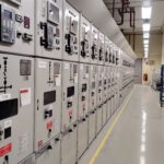
![Why MV Switchgear Fails: 5 Causes That Lead to Major Faults A 36 kV switchgear panel can sit closed for two years, carry load without complaint, and still fail on the one day you need it to clear a fault. That is the risk hiding behind a quiet panel. If the breaker won't trip, if protection doesn't detect the fault, or if insulation breaks down inside the cubicle, the result can be fire, arc flash, equipment loss, and a hard production stop. The real job is not waiting for failure and reacting later. It is spotting the warning signs before the panel runs out of margin. What counts as a switchgear failure Not every defect in a medium-voltage panel is a true failure. That distinction matters because reliability studies do not count every bad lamp, loose label, or minor nuisance the same way they count a breaker that won't trip. IEC 62271-1, clause 3.1.12, defines a major failure as a failure of switchgear and controlgear that causes the loss of one or more fundamental functions. It also says a major failure leads to an immediate change in system operating conditions, such as backup protection having to clear a fault, or forces unscheduled removal from service within 30 minutes. Major failures affect the core job of the panel In plain language, a major failure means the switchgear can no longer do one of its main jobs. Those jobs include switching, protection, monitoring, and control. If a fault occurs and the protection system does not detect it, that is a major failure. If the relay sends a trip command and the vacuum circuit breaker stays closed, that is also a major failure. The same goes for a situation where one bus section fails and the plant has to shift supply to another bus to keep running. The standard's wording about "immediate change in operating conditions" is useful because it points to real plant behavior, not theory. When primary protection fails and backup protection has to step in, the system has already moved into an abnormal state. If a breaker will not close because of a spring problem and must be removed from service at once, the equipment has lost its reliability. Minor failures are different, even if they still need attention A minor failure is anything that does not take away those core functions. An LED indication lamp that has gone dark is annoying, but it does not stop the panel from switching or protecting the system. A cosmetic defect may need correction, but it does not belong in the same category as a breaker mechanism that sticks. That distinction helps when you look at failure data. Most reliability studies focus on major failures, because those are the events that threaten safety, uptime, and equipment life. > A panel does not become dangerous only when it burns. It becomes dangerous the moment it can no longer switch, protect, or isolate a fault as intended. The five failure modes behind most serious problems Across published guidance and field experience, the same trouble spots keep showing up in MV switchgear. Insulation breakdown and mechanical faults sit near the top, while overheating, environmental stress, and aging keep chipping away at the system until something gives. A single medium voltage switchgear panel stands inside a clean and brightly lit industrial facility. [https://user-images.rightblogger.com/ai/f382171e-d1b1-4320-b7eb-289d9b53ee27/medium-voltage-switchgear-panel-dc9d5203.jpg] This quick summary helps frame where the risk usually sits: | Failure mode | Typical share or impact | Common triggers | Best early warning | | | | | | | Insulation failure | About 20% to 30% of failures | Partial discharge, insulation defects, contamination | PD testing or continuous PD monitoring | | Internal arc | Less about share, more about severity | Insulation breakdown, loose parts, human error, foreign objects | Arc detection plus proper panel design and rating | | Busbar and connection overheating | Major contributor within remaining failures | Poor joints, high contact resistance, loose terminations | Thermal inspection or continuous temperature monitoring | | Environmental and aging effects | Significant long-term driver | Moisture, dust, corrosion, seal failure, material degradation | Inspection, humidity monitoring, life assessment | | Mechanical failures | About 30% to 40% of failures | Trip coil issues, dry lubrication, worn parts, weak spring energy | Breaker monitoring and functional testing | The headline is simple. A switchgear failure usually starts as a small loss of margin, then turns into a major event when nobody is watching. Insulation failure usually starts where you can't see it Insulation failure is one of the biggest reasons MV switchgear fails. The hard part is that the panel can look healthy from the outside while the weakness grows inside cable insulation, busbar insulation, or instrument transformer resin. Partial discharge is small at first, then destructive Partial discharge starts when electrical stress concentrates inside tiny voids, impurities, or defects within insulation. In a cable, for example, a manufacturing void or a badly prepared termination can create a weak point. Stress collects there because the local dielectric strength is lower. Once the stress exceeds what that spot can withstand, a localized discharge starts. It is called "partial" because the discharge does not bridge the full insulation path at first. Still, the damage does not stay small. Repeated discharges eat away at the insulation until a much larger fault develops. A wood beam with termites offers a good comparison. The outside may still look sound, while the inside has already lost strength. By the time the damage is visible, the collapse is close. In MV panels, partial discharge often shows up in cable terminations, cable insulation itself, CT and VT epoxy insulation, and insulated busbar systems. The danger is that it rarely gives an obvious warning unless you are looking for it. For a broader research view, the review of medium-voltage switchgear fault detection [https://www.mdpi.com/1996-1073/15/18/6762] covers common detection methods and fault behavior in more detail. Periodic partial discharge testing helps, but it has a limit. You only see the panel at the moment of the test. Continuous monitoring fills the blind spot between maintenance visits. That difference matters more as the switchgear ages. Internal arc is where hidden weakness becomes immediate danger Internal arc is one of the worst events that can happen inside switchgear because it combines heat, pressure, smoke, and metal vapor in a confined space. It is not the same thing as a normal short circuit. An internal arc is a fault that develops inside the enclosure and puts people nearby at direct risk. Insulation failure can trigger it. So can a loose connection, a dropped tool, a foreign object left behind after maintenance, or simple human error. A screwdriver bridging two phases is enough to turn a routine task into a violent event. Besides fire damage, the smoke from an internal arc is hazardous on its own. That is why this topic is not only about asset protection. It is also about human safety. Modern panels may include arc detection systems that watch for both light and current. When they detect an arc, they send a trip command in milliseconds. It also pays to check whether the panel has been tested for internal arc classification, because that tells you how the equipment is expected to behave during this kind of fault. Heat at joints and contacts can undo a good panel Every electrical joint carries some risk. If the connection is poor, resistance rises. When current keeps flowing through that resistance, I squared R losses turn into heat, and heat becomes the start of the next failure. This issue appears again and again at busbar joints, cable terminations, breaker contacts, and earthing connections. The busbar connection between two panels is a common weak point. So is the cable end where termination quality depends on careful stripping, clean surfaces, correct materials, and proper tightening. In withdrawable breakers, primary contact engagement needs extra attention because poor seating can cause local hot spots. The physics is simple, but the effect is expensive. A small increase in contact resistance can push the temperature high enough to damage insulation, oxidize surfaces, weaken spring pressure, and set up the next arc fault. That is why overheating is a recurring theme in switchgear failure analysis, including this overview of switchgear failures and solutions [https://blog.exertherm.com/causes-of-switchgear-failures-and-solutions]. Good workmanship cuts most of this risk at the start. Joints need the right preparation, the right torque, and the right method from the manufacturer. After installation, thermal checks matter. A handheld IR inspection helps during rounds, but large sites with many panels often need more than occasional scans. Fixed thermal sensors on critical joints can track temperature all day and flag a problem before the panel forces a shutdown. Age and environment wear down the margin of safety Switchgear does not fail only because something was assembled badly. Time and environment also wear down the panel, even when operation looks normal. A typical service life is often described as about 25 to 30 years, though real life depends on duty, environment, maintenance, and design. Once equipment gets deep into that age range, the risk rises. Insulation can crack. Corrosion can creep across sheet metal and hardware. Seals can weaken in gas-filled compartments. Contacts wear. Springs lose strength. Materials that looked stable for years start to drift out of their original condition. Environmental stress speeds that process up. Moisture is a common problem because it lowers insulation resistance and can help contamination become conductive. Dust does the same thing when it settles where it should not. Some reported failure summaries tie a large share of busbar trouble to moisture and dust exposure, and this medium-voltage switchgear problem summary [https://www.green-energy-elec.com/common-problems-in-medium-voltage-switchgear/] highlights that pattern clearly. The fix depends on the site. Air-insulated panels in humid, dusty areas need more cleaning and inspection. Higher IP ratings help when the environment is harsh. In some applications, enclosed technologies such as GIS or solid-insulated systems reduce exposure. Humidity sensors inside selected panels also help, because they warn you when the room condition and the cubicle condition are drifting apart. Mechanical failures stop the breaker when it matters most Mechanical trouble is often the biggest single contributor to MV switchgear failure. That makes sense because a fault may be detected perfectly, yet the system still fails if the breaker mechanism cannot move. A breaker that has stayed closed for two years can look healthy, but that does not prove it will trip on demand. The trip coil may be open or shorted. Lubrication may have dried out or picked up contamination. Stored-energy springs may have weakened. Linkages may seize. Contacts may be worn. Any one of those problems can turn a valid trip command into a non-event. That is the nightmare scenario in a live plant. Fault current continues to flow because the breaker remains closed. Backup protection may clear the fault later, but the delay can mean heavier equipment damage, a wider outage, and greater risk to people nearby. Routine maintenance helps because it proves the mechanism can still move. Still, periodic checks have gaps. A breaker can pass a test in January and develop a mechanical issue in March. That is why breaker monitoring is gaining ground. Modern systems can track operating count, contact wear, gas or pressure status where relevant, opening and closing speed, and other health indicators that point to a weakening mechanism. For teams that already use connected diagnostics on breakers, tools such as a Pact series breaker diagnostic and testing interface [https://www.interestingautomation.com/schneider-electric-service-interface-kit-pact-series-circuit-breakers-installation-compatibility-expert-review/] show how live measurements and event data can shorten troubleshooting time and expose developing faults before a trip failure happens. > A breaker is not reliable because it stayed closed. It is reliable because you have evidence that it can still open. Why monitoring beats calendar-based maintenance alone Traditional maintenance still matters. Panels need cleaning, inspection, tightening, lubrication, and testing. Yet calendar-based maintenance only gives you snapshots. It cannot tell you what happened between visits. Monitoring changes that. A continuous system can watch temperature rise at a joint, catch partial discharge activity, track humidity inside a cubicle, and record breaker operation data around the clock. It also makes condition-based maintenance possible. Instead of opening equipment on a fixed calendar, you act when data shows the condition is changing. That approach is often the difference between "repair after failure" and "intervene before failure." On new switchgear, you may not need every sensor from day one. On older panels, on hard-worked breakers, or across a large fleet, the case for monitoring becomes much stronger. A plant-wide supervision layer also helps because raw data is not enough by itself. Operators need one place to see alarms, status changes, and events in context. Platforms focused on real-time monitoring with Schneider EPAS [https://www.interestingautomation.com/schneider-electric-epas/] show why visibility matters when a feeder trips or a breaker changes state. Faster fault isolation starts with seeing the right information at the right time. Final thoughts The most dangerous switchgear failures do not start with a dramatic event. They start with a missed warning, a weak joint, a dry mechanism, or insulation that is breaking down in silence. If there is one takeaway to keep, it is this: reliability needs proof. A breaker that has been closed for two years is only comforting when you know it can still trip today, and the rest of the panel can still do its core job when the fault arrives.](https://www.interestingautomation.com/wp-content/uploads/2026/05/Why-MV-Switchgear-Fails-5-Causes-That-Lead-to-Major-Faults-150x150.jpg)