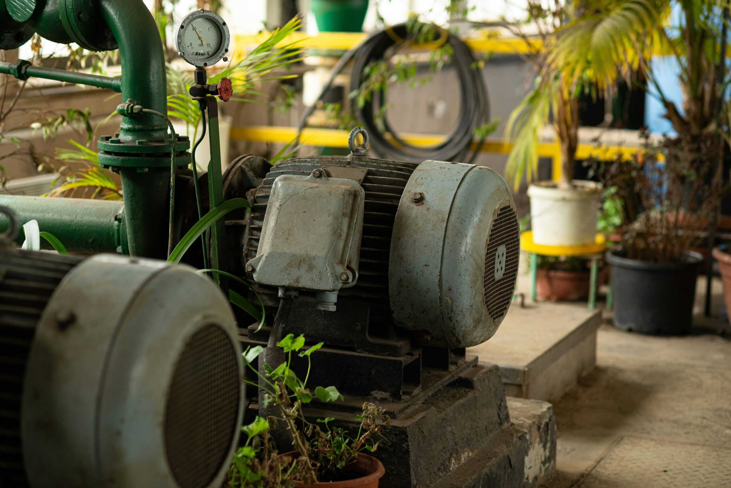
Induction motors consume a huge share of industrial electricity, often quoted at around 60 to 70 percent. That tells you how central they are to modern plants, from cement and steel to textiles, chemicals, water systems, and HVAC.
The same basic machine also shows up in homes, inside fans, washing machines, air conditioners, and coolers. Its popularity isn’t an accident. It comes from a simple fact: an induction motor gives industry most of what it needs, without a lot of fuss.
The checklist every industrial motor must meet
A factory doesn’t pick a motor because it looks good on paper. It picks a motor that can survive real work. In many plants, motors run for 8 hours, 12 hours, or all day without stopping. Some only shut down during maintenance. That makes reliability the first test.
When a critical motor fails, the motor itself may not be the biggest loss. Downtime usually hurts more. A failed motor on a boiler feed pump, cooling tower pump, fan, conveyor, or process line can slow production or stop it cold. That’s why plants want equipment they can trust.
The second big need is low maintenance. A plant may have hundreds, sometimes thousands, of motors. If each one needed frequent brush changes, commutator cleaning, or special inspection, the maintenance team would stay buried in routine work. Simple upkeep matters more than many people realize.
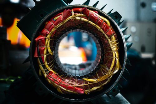
Then come rugged construction, reasonable cost, simple operation, and good efficiency with easy availability. Industrial motors face dust, heat, moisture, vibration, voltage swings, and changing loads. They also have to make financial sense at scale. A small price gap doesn’t matter much for one motor, but across a full plant it becomes a serious line item.
This quick table sums up that checklist:
| What industry expects | Why it matters in daily operation |
|---|---|
| Reliability | A failed motor can stop a process and create costly downtime |
| Low maintenance | Large motor fleets need simple, repeatable upkeep |
| Rugged construction | Plants expose motors to heat, dust, vibration, and moisture |
| Reasonable cost | Purchase, repair, and operating costs all add up |
| Simple operation | Motors should work with the plant’s AC power system |
| Efficiency and availability | Energy use, spare parts, and replacement time affect total cost |
That list explains why induction motors keep winning. As the OSU Energy Efficiency Center’s overview of common industrial motor types notes, industry keeps coming back to motors that are simple, reliable, and economical.
Why induction motors match that checklist so well
The standard industrial choice is the three-phase, squirrel-cage induction motor. Its design is plain compared with some other motor types, and that plainness is exactly why it works so well in tough service.
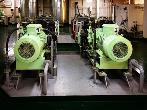
A typical industrial induction motor is built for long, repetitive duty.
Simple construction keeps failure points low
A squirrel-cage induction motor has stator windings and a rotor that doesn’t need a direct electrical connection. Rotor current appears through electromagnetic induction. Because of that, there are no brushes and no commutator in the common squirrel-cage design.
That detail matters. In DC motors, brushes and commutators wear down, create sparks, and need more attention. In an induction motor, those wear parts are gone. Fewer parts rubbing, switching, and wearing out means fewer chances for failure.
This is one reason plants trust induction motors for continuous-duty work. They can run for long hours without the sort of routine attention that more complex machines often need. For larger drives, protection still matters, especially when a fault could damage windings or stop a line. In medium-voltage applications, medium voltage motor fault protection methods play a big role in keeping critical equipment online.
If you want a concise refresher on the main parts, Schneider Electric’s induction motor primer lays out the stator, rotor, and common types clearly.
Low maintenance makes plant-wide upkeep practical
No motor is maintenance-free. Bearings can fail. Windings can overheat. Insulation ages. Dust can block ventilation paths. Overload conditions can shorten life. Still, compared with many other motor types, induction motors are easier to keep healthy.
That difference becomes obvious in a large plant. A site with 500 motors needs standard inspection routines, common spare parts, and troubleshooting steps technicians already know. Induction motors fit that model well. Maintenance teams can build repeatable practices around them instead of managing several different upkeep programs.
This is where popularity creates its own advantage. Because induction motors are everywhere, technicians understand them, vendors stock them, and replacement planning is easier. A plant doesn’t want to depend on a motor that only one supplier handles or only a few specialists can repair.
Rugged design handles harsh industrial conditions
Industrial environments are rarely gentle. Cement plants throw dust into the air. Steel plants bring heat. Pumping stations deal with moisture. Manufacturing lines add vibration, shocks, and shifting mechanical loads. Motors in these spaces have to be tough.
Squirrel-cage induction motors are known for that toughness. Their rotor construction is simple, solid, and mechanically strong. There aren’t delicate rotor windings in the common design, and that helps them stand up to rougher service.
As a result, you see induction motors almost everywhere heavy work happens. They drive pumps, fans, blowers, conveyors, compressors, workshop machines, and HVAC systems. The same motor type can live in a hot plant room, a dusty mill, or a utility building without needing a totally different maintenance philosophy.
That ruggedness also helps during the less glamorous parts of plant life, such as transport, installation, and handling during shutdowns. Equipment that tolerates real site conditions usually earns a long future in industry.
They fit the power system and the budget
Most industrial distribution systems are AC systems, so induction motors fit naturally. A three-phase induction motor can connect directly to the plant’s available supply, depending on the application and the starting method. That makes operation more straightforward than a motor that needs extra electrical arrangements for normal service.
Plants also have several starting options available. Smaller or less demanding applications may use direct-on-line starting. Other duties may call for star-delta starters, autotransformer starters, soft starters, or variable frequency drives. That flexibility helps engineers match the motor to the load and the network.
Cost matters just as much. Induction motors are mass-produced and standardized across a huge range of sizes and ratings. Because the design is simple and widely used, purchase costs are often reasonable, and repair costs tend to stay under control too. That appeals to maintenance teams, project engineers, purchasing groups, and plant owners for the same reason: scale magnifies every dollar.
Efficiency and availability matter more than brochure claims
A motor’s purchase price gets attention because it’s visible. Its electricity use often matters more because it never stops showing up on the bill.
Over a motor’s lifetime, the cost of electricity is usually much higher than the initial cost of the motor.
That is why efficiency matters so much in fans, pumps, and other loads that run for long hours every day. Modern induction motors are available in high-efficiency classes, so they offer a strong balance of performance, operating cost, and upfront price.
Availability is the other half of the story. Induction motors come in a wide range of ratings, speeds, frame sizes, mounting styles, enclosure types, and efficiency levels. That wide catalog makes replacement easier and spare planning simpler. A technically strong motor loses its shine fast if no one stocks it and replacement takes weeks.
Some plants chasing the highest possible efficiency compare induction motors with high-efficiency IE5 synchronous reluctance motors. Even then, induction motors remain the default in many applications because they balance efficiency with cost, familiarity, and easy field support.
The limits plants still have to manage
Induction motors are popular because they solve a lot of real problems. They are not perfect, and pretending otherwise leads to poor design choices.
High starting current can stress the system
When an induction motor starts direct-on-line, it can draw several times its full-load current. That surge can create voltage dips and electrical stress, especially on weaker systems or large motor feeders.
Because of that, bigger motors often need controlled starting methods. Star-delta starters, autotransformer starters, soft starters, and variable frequency drives all help reduce the strain. In heavier applications, a medium voltage soft starter for heavy-duty motors can limit starting current and reduce mechanical shock on the load.
Speed control is limited on fixed-frequency supply
On a normal fixed-frequency AC system, induction motor speed is tied mainly to supply frequency and the number of poles. That means speed is not easily adjustable if the motor runs straight from the line.
For many traditional plant duties, that isn’t a problem. Fans, pumps, and simple process loads often run well at near-constant speed. But when the process needs wide and smooth speed control, a VFD changes the picture. With a drive in place, one of the classic limits of the induction motor becomes much less serious.
Power factor is not unity
Induction motors need magnetizing current to create the magnetic field. Part of the current supports that field instead of turning fully into useful mechanical output. Because of this, the motor’s power factor is not unity, especially at light load.
That has money attached to it. Poor power factor can raise system losses and affect utility charges or plant efficiency targets. So plants deal with it through proper motor sizing, capacitor banks, and broader power factor correction systems.
Starting torque is not right for every load
Some applications need strong torque at startup. Induction motors do not all deliver the same starting torque, and a standard design may fall short for certain heavy or hard-to-start loads.
When startup torque is a key requirement, engineers may choose a special rotor design, a slip-ring induction motor, or a different motor type. This doesn’t reduce the value of induction motors. It simply shows that motor selection always depends on the job.
Final thoughts
Induction motors keep their place because they match the real needs of industry. They are reliable, easy to maintain, tough enough for harsh spaces, practical on AC power systems, and widely available when a plant needs a replacement fast.
That mix is hard to beat. The same basic motor that spins a fan at home can also keep a pump, blower, or conveyor running in a demanding plant, and that kind of practical strength is why induction motors still dominate.


![Why MV Switchgear Fails: 5 Causes That Lead to Major Faults A 36 kV switchgear panel can sit closed for two years, carry load without complaint, and still fail on the one day you need it to clear a fault. That is the risk hiding behind a quiet panel. If the breaker won't trip, if protection doesn't detect the fault, or if insulation breaks down inside the cubicle, the result can be fire, arc flash, equipment loss, and a hard production stop. The real job is not waiting for failure and reacting later. It is spotting the warning signs before the panel runs out of margin. What counts as a switchgear failure Not every defect in a medium-voltage panel is a true failure. That distinction matters because reliability studies do not count every bad lamp, loose label, or minor nuisance the same way they count a breaker that won't trip. IEC 62271-1, clause 3.1.12, defines a major failure as a failure of switchgear and controlgear that causes the loss of one or more fundamental functions. It also says a major failure leads to an immediate change in system operating conditions, such as backup protection having to clear a fault, or forces unscheduled removal from service within 30 minutes. Major failures affect the core job of the panel In plain language, a major failure means the switchgear can no longer do one of its main jobs. Those jobs include switching, protection, monitoring, and control. If a fault occurs and the protection system does not detect it, that is a major failure. If the relay sends a trip command and the vacuum circuit breaker stays closed, that is also a major failure. The same goes for a situation where one bus section fails and the plant has to shift supply to another bus to keep running. The standard's wording about "immediate change in operating conditions" is useful because it points to real plant behavior, not theory. When primary protection fails and backup protection has to step in, the system has already moved into an abnormal state. If a breaker will not close because of a spring problem and must be removed from service at once, the equipment has lost its reliability. Minor failures are different, even if they still need attention A minor failure is anything that does not take away those core functions. An LED indication lamp that has gone dark is annoying, but it does not stop the panel from switching or protecting the system. A cosmetic defect may need correction, but it does not belong in the same category as a breaker mechanism that sticks. That distinction helps when you look at failure data. Most reliability studies focus on major failures, because those are the events that threaten safety, uptime, and equipment life. > A panel does not become dangerous only when it burns. It becomes dangerous the moment it can no longer switch, protect, or isolate a fault as intended. The five failure modes behind most serious problems Across published guidance and field experience, the same trouble spots keep showing up in MV switchgear. Insulation breakdown and mechanical faults sit near the top, while overheating, environmental stress, and aging keep chipping away at the system until something gives. A single medium voltage switchgear panel stands inside a clean and brightly lit industrial facility. [https://user-images.rightblogger.com/ai/f382171e-d1b1-4320-b7eb-289d9b53ee27/medium-voltage-switchgear-panel-dc9d5203.jpg] This quick summary helps frame where the risk usually sits: | Failure mode | Typical share or impact | Common triggers | Best early warning | | | | | | | Insulation failure | About 20% to 30% of failures | Partial discharge, insulation defects, contamination | PD testing or continuous PD monitoring | | Internal arc | Less about share, more about severity | Insulation breakdown, loose parts, human error, foreign objects | Arc detection plus proper panel design and rating | | Busbar and connection overheating | Major contributor within remaining failures | Poor joints, high contact resistance, loose terminations | Thermal inspection or continuous temperature monitoring | | Environmental and aging effects | Significant long-term driver | Moisture, dust, corrosion, seal failure, material degradation | Inspection, humidity monitoring, life assessment | | Mechanical failures | About 30% to 40% of failures | Trip coil issues, dry lubrication, worn parts, weak spring energy | Breaker monitoring and functional testing | The headline is simple. A switchgear failure usually starts as a small loss of margin, then turns into a major event when nobody is watching. Insulation failure usually starts where you can't see it Insulation failure is one of the biggest reasons MV switchgear fails. The hard part is that the panel can look healthy from the outside while the weakness grows inside cable insulation, busbar insulation, or instrument transformer resin. Partial discharge is small at first, then destructive Partial discharge starts when electrical stress concentrates inside tiny voids, impurities, or defects within insulation. In a cable, for example, a manufacturing void or a badly prepared termination can create a weak point. Stress collects there because the local dielectric strength is lower. Once the stress exceeds what that spot can withstand, a localized discharge starts. It is called "partial" because the discharge does not bridge the full insulation path at first. Still, the damage does not stay small. Repeated discharges eat away at the insulation until a much larger fault develops. A wood beam with termites offers a good comparison. The outside may still look sound, while the inside has already lost strength. By the time the damage is visible, the collapse is close. In MV panels, partial discharge often shows up in cable terminations, cable insulation itself, CT and VT epoxy insulation, and insulated busbar systems. The danger is that it rarely gives an obvious warning unless you are looking for it. For a broader research view, the review of medium-voltage switchgear fault detection [https://www.mdpi.com/1996-1073/15/18/6762] covers common detection methods and fault behavior in more detail. Periodic partial discharge testing helps, but it has a limit. You only see the panel at the moment of the test. Continuous monitoring fills the blind spot between maintenance visits. That difference matters more as the switchgear ages. Internal arc is where hidden weakness becomes immediate danger Internal arc is one of the worst events that can happen inside switchgear because it combines heat, pressure, smoke, and metal vapor in a confined space. It is not the same thing as a normal short circuit. An internal arc is a fault that develops inside the enclosure and puts people nearby at direct risk. Insulation failure can trigger it. So can a loose connection, a dropped tool, a foreign object left behind after maintenance, or simple human error. A screwdriver bridging two phases is enough to turn a routine task into a violent event. Besides fire damage, the smoke from an internal arc is hazardous on its own. That is why this topic is not only about asset protection. It is also about human safety. Modern panels may include arc detection systems that watch for both light and current. When they detect an arc, they send a trip command in milliseconds. It also pays to check whether the panel has been tested for internal arc classification, because that tells you how the equipment is expected to behave during this kind of fault. Heat at joints and contacts can undo a good panel Every electrical joint carries some risk. If the connection is poor, resistance rises. When current keeps flowing through that resistance, I squared R losses turn into heat, and heat becomes the start of the next failure. This issue appears again and again at busbar joints, cable terminations, breaker contacts, and earthing connections. The busbar connection between two panels is a common weak point. So is the cable end where termination quality depends on careful stripping, clean surfaces, correct materials, and proper tightening. In withdrawable breakers, primary contact engagement needs extra attention because poor seating can cause local hot spots. The physics is simple, but the effect is expensive. A small increase in contact resistance can push the temperature high enough to damage insulation, oxidize surfaces, weaken spring pressure, and set up the next arc fault. That is why overheating is a recurring theme in switchgear failure analysis, including this overview of switchgear failures and solutions [https://blog.exertherm.com/causes-of-switchgear-failures-and-solutions]. Good workmanship cuts most of this risk at the start. Joints need the right preparation, the right torque, and the right method from the manufacturer. After installation, thermal checks matter. A handheld IR inspection helps during rounds, but large sites with many panels often need more than occasional scans. Fixed thermal sensors on critical joints can track temperature all day and flag a problem before the panel forces a shutdown. Age and environment wear down the margin of safety Switchgear does not fail only because something was assembled badly. Time and environment also wear down the panel, even when operation looks normal. A typical service life is often described as about 25 to 30 years, though real life depends on duty, environment, maintenance, and design. Once equipment gets deep into that age range, the risk rises. Insulation can crack. Corrosion can creep across sheet metal and hardware. Seals can weaken in gas-filled compartments. Contacts wear. Springs lose strength. Materials that looked stable for years start to drift out of their original condition. Environmental stress speeds that process up. Moisture is a common problem because it lowers insulation resistance and can help contamination become conductive. Dust does the same thing when it settles where it should not. Some reported failure summaries tie a large share of busbar trouble to moisture and dust exposure, and this medium-voltage switchgear problem summary [https://www.green-energy-elec.com/common-problems-in-medium-voltage-switchgear/] highlights that pattern clearly. The fix depends on the site. Air-insulated panels in humid, dusty areas need more cleaning and inspection. Higher IP ratings help when the environment is harsh. In some applications, enclosed technologies such as GIS or solid-insulated systems reduce exposure. Humidity sensors inside selected panels also help, because they warn you when the room condition and the cubicle condition are drifting apart. Mechanical failures stop the breaker when it matters most Mechanical trouble is often the biggest single contributor to MV switchgear failure. That makes sense because a fault may be detected perfectly, yet the system still fails if the breaker mechanism cannot move. A breaker that has stayed closed for two years can look healthy, but that does not prove it will trip on demand. The trip coil may be open or shorted. Lubrication may have dried out or picked up contamination. Stored-energy springs may have weakened. Linkages may seize. Contacts may be worn. Any one of those problems can turn a valid trip command into a non-event. That is the nightmare scenario in a live plant. Fault current continues to flow because the breaker remains closed. Backup protection may clear the fault later, but the delay can mean heavier equipment damage, a wider outage, and greater risk to people nearby. Routine maintenance helps because it proves the mechanism can still move. Still, periodic checks have gaps. A breaker can pass a test in January and develop a mechanical issue in March. That is why breaker monitoring is gaining ground. Modern systems can track operating count, contact wear, gas or pressure status where relevant, opening and closing speed, and other health indicators that point to a weakening mechanism. For teams that already use connected diagnostics on breakers, tools such as a Pact series breaker diagnostic and testing interface [https://www.interestingautomation.com/schneider-electric-service-interface-kit-pact-series-circuit-breakers-installation-compatibility-expert-review/] show how live measurements and event data can shorten troubleshooting time and expose developing faults before a trip failure happens. > A breaker is not reliable because it stayed closed. It is reliable because you have evidence that it can still open. Why monitoring beats calendar-based maintenance alone Traditional maintenance still matters. Panels need cleaning, inspection, tightening, lubrication, and testing. Yet calendar-based maintenance only gives you snapshots. It cannot tell you what happened between visits. Monitoring changes that. A continuous system can watch temperature rise at a joint, catch partial discharge activity, track humidity inside a cubicle, and record breaker operation data around the clock. It also makes condition-based maintenance possible. Instead of opening equipment on a fixed calendar, you act when data shows the condition is changing. That approach is often the difference between "repair after failure" and "intervene before failure." On new switchgear, you may not need every sensor from day one. On older panels, on hard-worked breakers, or across a large fleet, the case for monitoring becomes much stronger. A plant-wide supervision layer also helps because raw data is not enough by itself. Operators need one place to see alarms, status changes, and events in context. Platforms focused on real-time monitoring with Schneider EPAS [https://www.interestingautomation.com/schneider-electric-epas/] show why visibility matters when a feeder trips or a breaker changes state. Faster fault isolation starts with seeing the right information at the right time. Final thoughts The most dangerous switchgear failures do not start with a dramatic event. They start with a missed warning, a weak joint, a dry mechanism, or insulation that is breaking down in silence. If there is one takeaway to keep, it is this: reliability needs proof. A breaker that has been closed for two years is only comforting when you know it can still trip today, and the rest of the panel can still do its core job when the fault arrives.](https://www.interestingautomation.com/wp-content/uploads/2026/05/Why-MV-Switchgear-Fails-5-Causes-That-Lead-to-Major-Faults-150x150.jpg)