In continuous-process industries, an unexpected motor trip doesn’t just halt a single machine—it can stall an entire production line. While traditional thermal overload relays only react after a fault has occurred, modern industrial automation demands predictive insight.
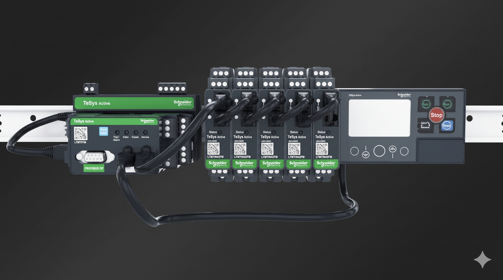
The Schneider Electric TeSys Tera (LTMT) intelligent motor management system bridges the gap between electrical protection and industrial IoT. By decoupling current and voltage measurement from the main processing unit, TeSys Tera delivers high-accuracy motor protection, starter control, and real-time energy metering in a compact, modular footprint designed for intelligent Motor Control Centers (iMCCs).
Table of Contents
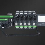
Understanding the Modular LTMT Architecture
Traditional motor management relays house current transformers (CTs), voltage inputs, and communication ports inside a single bulky chassis. In cramped MCC withdrawable drawers, routing heavy power cables through a fixed control unit creates installation bottlenecks and complicates maintenance.
TeSys Tera solves this by splitting the system into four specialized, interconnected hardware modules:
1. LTMT Main Control Unit
Acting as the central processor, the main unit executes protection algorithms, starter control logic, and network communications. It features 4 built-in digital inputs (internally or externally powered) and 3 relay outputs (2 NO + 1 NO/NC). Depending on your control panel architecture, the main unit is available in two power supply variants across three major industrial protocols:
| Catalog Number | Communication Protocol | Control Supply Voltage | Key Network Interface |
| LTMTEFM | EtherNet/IP & Modbus TCP | 100–240 V AC/DC | Dual RJ45 ports (supports HSR ring redundancy) |
| LTMTEBD | EtherNet/IP & Modbus TCP | 24 V DC | Dual RJ45 ports (supports HSR ring redundancy) |
| LTMTMFM | Modbus RTU | 100–240 V AC/DC | RS-485 2-wire interface |
| LTMTPFM / LTMTPBD | PROFIBUS DP | 100–240 V AC/DC or 24 V DC | SUB-D 9 or terminal block (up to 12 Mbit/s) |
2. LTMTCT & LTMTCTV Sensor Modules
Instead of pulling motor leads up to the control relay, the compact sensor module mounts directly in the power path.
- Current Range: Direct measurement from 0.3 A to 100 A across four sensor bands (0.3–3 A, 2.5–25 A, 7–70 A, and 10–100 A), scalable up to 810 A using external current transformers.
- Voltage & Power Sensing (LTMTCTV): Measures line-to-line voltages up to 690 V AC, enabling true active/reactive power, power factor, and Total Harmonic Distortion (THD) calculations.
3. LTMT Expansion Modules
For complex starter applications requiring additional field interlocks or analog telemetry, expansion modules (such as the LTMTIN42FM) snap directly onto the main unit, adding isolated digital inputs, relay outputs, and analog I/O without requiring extra power supplies.
4. LTMTCUF Control Operator Unit
Mounted on the MCC cabinet door, this local Human-Machine Interface (HMI) allows technicians to view real-time motor parameters, acknowledge trip alarms, and perform local start/stop operations without opening the enclosure door.
Comprehensive Protection: Beyond Thermal Overload
Standard overload relays estimate motor heating based solely on current draw. Because TeSys Tera monitors 3-phase current, 3-phase voltage, temperature sensor inputs, and power factor simultaneously, it protects both the motor windings and the driven mechanical load.
- Thermal & Temperature Protection: Utilizes an advanced thermal memory model alongside direct motor winding temperature monitoring (via PTC, NTC, or PT100 sensors) to prevent insulation breakdown even during frequent starts or loss of ambient cooling.
- Mechanical Jam & Underload Detection: An abrupt spike in current triggers the Stalled/Locked Rotor protection to prevent shaft shear on conveyors or crushers. Conversely, a sudden drop in active power or current triggers Underload/Under-power protection—instantly catching dry-running pumps or broken drive belts before mechanical damage occurs.
- Supply Quality & Phase Protection: Protects against voltage sags, over-voltage, phase loss, phase reversal, and voltage/current imbalance before the motor even attempts to start.
- Internal & External Ground Fault: Detects insulation degradation early via internal residual current calculation or an external core-balance earth leakage CT.
- Anti-Backspin Timer: Prevents vertical turbine pumps from restarting while water is still flowing backward through the impeller, eliminating catastrophic torque shock.
Power Grid Resiliency: Voltage Dip Management & Auto-Restart
In heavy process plants (such as petrochemicals, cement, and water treatment), a momentary grid voltage dip of a few hundred milliseconds can drop out hundreds of contactors simultaneously. Re-energizing all motors at once upon power restoration can trip the main substation breaker.
TeSys Tera automates grid recovery through three built-in power continuity functions:
- Voltage Dip Management: Differentiates between a momentary voltage sag and a true power outage.
- Automated Load Shedding: Sheds non-essential motors during peak demand or brownouts to keep critical process loads running.
- Staggered Auto-Restart: Tracks the exact duration of a voltage dip. If power returns within a safe window, TeSys Tera restarts critical motors immediately or executes a staggered, time-delayed restart sequence to prevent transformer inrush trips.
Technical Specifications at a Glance
| Parameter | TeSys Tera (LTMT) Specification |
| Rated Insulation Voltage ($U_i$) | Up to 690 V AC (conforming to IEC 60185 / IEC 60947-4-1) |
| Short-Circuit Withstand | Up to 100 kA |
| Measurement Accuracy | Current: $\pm 1\%$ (up to 25 A) / $\pm 3\%$ (up to 100 A); Voltage: $\pm 1\%$ (110–690 V) |
| Energy & THD Accuracy | Active/Reactive Energy: $\pm 2\text{–}5\%$; THD: $\pm 2\%$ |
| Operating Temperature | -20°C to +70°C (-4°F to +158°F) without derating up to 2,000 m |
| Mechanical Robustness | 4 Gn vibration (plate mounted); 15 Gn shock (11 ms half-sine wave) |
| Main Unit Dimensions (H × W × D) | 45 mm × 112 mm × 90 mm (DIN rail or plate mountable) |
Upgrading Legacy MCCs: TeSys Tera vs. Traditional Relays
When specifying protection for new or retrofitted Motor Control Centers, engineering teams typically weigh basic electronic overload relays against full intelligent motor management systems:
- Wiring Efficiency: Traditional setups require separate current transformers, voltage transducers, power meters, and auxiliary relays wired to a PLC input card. TeSys Tera consolidates all four devices into a single network node, cutting drawer wiring time by over 40%.
- Predictive Diagnostics: Instead of a generic “Fault” contact, TeSys Tera logs timestamped trip histories, tracks thermal capacity utilization, counts motor starts, and streams Total Harmonic Distortion (THD) data directly to SCADA systems.
- High-Availability Networking: Dual Ethernet ports supporting High-availability Seamless Redundancy (HSR) ensure that if a single network cable is severed inside an MCC lineup, communication with the PLC remains uninterrupted with zero packet loss.
Frequently Asked Questions (FAQ)
How do I select the right TeSys Tera sensor module for my motor?
Match the sensor module to your motor’s Full Load Amps (FLA) and monitoring requirements. Choose an LTMTCT module if you only need current-based protection, or an LTMTCTV module if you require voltage protection, power factor monitoring, load shedding, and energy metering. For motors drawing between 0.3 A and 100 A, route the power conductors directly through the sensor window; for motors between 100 A and 810 A, pair a low-range sensor module with external protection CTs.
Can TeSys Tera reset to factory defaults without a laptop?
Yes, provided the motor is in the Stop state (reset requests are ignored during Start or Run states for safety). Press and hold the physical reset button on the LTMT main unit for 15 to 20 seconds until the Trip/Alarm LED blinks blue to restore default parameters.
What starter configurations does TeSys Tera support?
TeSys Tera includes pre-programmed control logic for Direct-On-Line (DOL), Reversing, Star-Delta (Wye-Delta), Two-Speed, and Soft Starter / Variable Frequency Drive (VFD) bypass applications, eliminating the need to write custom PLC interlocking logic for standard motor feeders.