A power factor reading tells you more than how well a system uses electricity. It also tells you whether the system is pulling reactive power from the grid or sending reactive power back.
That matters because real electrical systems are rarely neat, pure resistor circuits. They are full of motors, transformers, lighting, cables, and capacitor banks, so voltage and current often drift out of step. Once you picture that timing difference, leading vs lagging power factor stops feeling abstract and starts looking like a clear story about the load.
The story starts with three kinds of power.
Table of Contents
Power factor basics, in plain English
Power factor is a ratio, but it points to something practical. It tells you how much of the total power demand is doing useful work.
If a system draws 100 units of total power from the source, but only 80 of those units turn into real work, the rest is tied up in the back-and-forth exchange needed to support magnetic or electric fields. That is why power factor matters so much in AC systems.
Active power, reactive power, and apparent power explained simply
Active power is the part that does the job. It turns a motor shaft, heats an element, or lights a lamp. It is measured in watts.
Reactive power does not produce that final output on its own, but it is still part of how AC equipment works. Motors and transformers need magnetic fields. Capacitors store and release energy in electric fields. That exchange is reactive power, and it is measured in VAr.
Apparent power is the total demand placed on the source. It combines active and reactive power, and it is measured in VA. Power factor is the share of apparent power that becomes active power.
A separate What is Power Factor explainer covers the same idea with visual sketches.
When current lags voltage, the system is pulling reactive power. When current leads voltage, it is pushing reactive power back.
Why mixed loads change the picture in real life
Pure textbook circuits are useful for learning, but plants and buildings do not run that way. A facility might have lighting, heater loads, induction motors, transformers, drives, and correction capacitors all connected to the same network.
Because of that mix, power factor is rarely a perfect 1.0. Some loads pull current late. Others push it early. The source still has to carry the total demand.
That is why engineers watch power factor so closely. A poor value often means higher current, more losses, less spare capacity, and sometimes utility penalties. In the field, meters and sensors such as PowerLogic PowerTag can report active, reactive, and apparent power side by side, which makes the picture much easier to read.
Why unity power factor is the ideal, but not the usual case
Unity power factor is the cleanest case. Voltage and current rise, fall, cross zero, and hit their peaks at the same time.
That only happens in a purely resistive circuit. There is no inductance pulling current behind, and no capacitance pushing it ahead.
What a purely resistive load looks like
The example circuit uses a 230 V, 50 Hz supply feeding a 60 ohm resistive load. In a case like this, the voltage and current waveforms sit on top of each other. Their positive peaks match. Their negative peaks match. Their zero crossings match too.
That in-phase relationship is the visual clue for unity power factor. Simple resistive elements behave this way because they do not store energy in magnetic or electric fields. They turn electrical energy straight into heat or another direct output.
In real industry, though, a truly pure resistive system is rare. Most plants do not run on heaters alone. They run on mixed loads, and mixed loads change the phase relationship.
Why the power triangle collapses into a straight line
In the sample calculation, active power is shown as 181 W and reactive power is zero. Since there is no reactive component, apparent power is the same as active power.
That means the power triangle has no height. It becomes a straight line along the active power axis. There is no upward or downward reactive side because the circuit is not borrowing or returning reactive power.
So unity power factor is the best teaching example. It shows the ideal case where all supplied power is useful power. It is also why a unity power factor is the target most systems try to approach, even if they never stay there perfectly.
Why lagging power factor shows up so often in industry
Lagging power factor is the one you will see most often in plants, workshops, and commercial buildings. The reason is simple: industry runs on inductive equipment.
Motors, transformers, and coils are everywhere, and all of them affect the timing between voltage and current.
How inductive loads pull current behind voltage
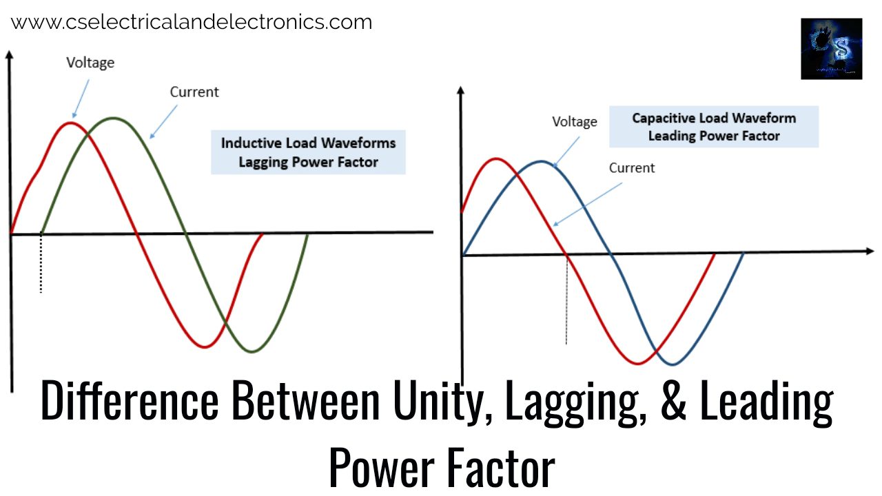
An inductive load has windings or coils. When AC flows through that winding, the load builds a magnetic field. Because an inductor resists changes in current, the current does not rise instantly with the voltage. It falls behind by some angle.
In a purely inductive circuit, that phase shift would be 90 degrees. Real systems are not pure, so the angle is usually smaller because resistance and other elements are present too.
That is the core of lagging power factor. Voltage gets there first. Current follows later.
Induction motors are the classic example. A transformer behaves the same way. Both need magnetizing current, and that magnetizing demand is reactive.
What positive reactive power means for the grid
In the worked example, active power is 515 W, reactive power is 413 VAr, and apparent power is 671 VA. The calculated power factor is 0.768 lagging.
Those numbers show the difference between total demand and useful output. The source has to supply 671 VA, but only 515 W becomes real work. The rest is reactive demand tied to the inductive behavior of the circuit.
A positive reactive power value means the system is consuming reactive power from the supply. In other words, the grid or upstream source is helping support the load’s magnetic field.
This is one reason power quality software matters. Tools built for power factor monitoring with PME can show that drift in real time across feeders and loads.
The practical signs you will see in plant equipment
A lagging power factor is normal up to a point. Still, when it drops too far, the system pays for it with higher current for the same useful power.
That extra current can mean more voltage drop, more heating in cables, and less usable capacity in transformers, switchgear, and generators. In some facilities, it also brings utility penalties or pushes equipment closer to its limits.
Modern devices can expose that behavior directly. Some breaker communication systems include circuit breaker power factor data along with current, voltage, and energy values. That makes it easier to spot a feeder that is dragging the whole plant into a low lagging power factor.
The common fix is local capacitive support. Instead of making the grid provide all the reactive power, capacitor banks supply part of it near the load.
Leading power factor, and why it usually points to too much capacitance
Leading power factor is the mirror image of lagging power factor. Here, current reaches its waveform points before voltage does.
That behavior is tied to capacitive circuits.
How capacitive loads shift the waveform
The sample circuit uses a 230 V, 50 Hz source with a 50 ohm resistor and a 100 microfarad capacitor. In that kind of circuit, current gets a head start and voltage trails behind.
In a purely capacitive circuit, the phase shift would be 90 degrees. Real circuits are mixed, so the angle depends on the actual resistance and capacitance in the path.
Capacitors behave this way because they oppose changes in voltage. Current adjusts first while the capacitor charges and discharges, so the current waveform leads.
When negative reactive power appears
In the example, active power is 753 W, reactive power is -479 VAr, and apparent power is 892 VA. The power factor is 0.844 leading.
The sign on reactive power matters. A negative reactive power value means the circuit is delivering reactive power back toward the source. The system is no longer asking the grid for that support. It is supplying it.
The power triangle flips too. Active power still sits on the horizontal axis, but reactive power drops below it because the reactive part is negative.
That is the signature of a leading power factor.
Why oversized capacitor banks can create problems
A leading power factor is much less common in normal plant operation. Most sites do not have enough natural capacitance to create it on their own.
It usually shows up after power factor correction is added and pushed too far. A capacitor bank that is too large, or one that stays connected when the inductive load has fallen, can overcorrect the system.
That is also where a common mistake appears. A capacitor bank is often called a “capacitive load,” but that is not accurate in this context. A load consumes power. A capacitor bank supplies reactive power to the system, so it does not behave like a normal consuming load.
In some installations, correction banks are switched with vacuum contactors for power factor correction. If the bank is oversized or badly staged, the system can move past unity and into leading power factor. When that happens, reactors or other inductive elements may be needed to pull the balance back.
Leading vs lagging power factor, which one is better in practice?
The short answer is that neither extreme is the goal. A system usually runs best when power factor stays close to unity.
Lagging power factor is common and often expected because most real loads are inductive. Leading power factor is less common and often points to overcorrection or excess capacitance.
This quick comparison makes the difference easier to scan:
| Type | Current relative to voltage | Reactive power sign | Common cause | What it means |
|---|---|---|---|---|
| Unity | In phase | Zero | Purely resistive load | All apparent power is active power |
| Lagging | Current lags | Positive | Motors, transformers, coils | System draws reactive power from the source |
| Leading | Current leads | Negative | Capacitors, overcorrection | System sends reactive power back to the source |
Most operating problems appear when a plant drifts too far from the unity side of that table, in either direction.
Why power factor close to unity is usually the real goal
A power factor near 1.0 means the source is not carrying much extra current for reactive demand. That usually means better use of cables, transformers, and switchgear.
It also means the apparent power and active power are closer together. That gap matters because equipment is sized by what it must carry, not only by the useful work delivered.
Plants do not chase “lagging” or “leading.” They chase a power factor close to 1.
How to tell whether a system needs correction or balance
A lagging reading usually points to inductive demand, so the system may need capacitive support. A leading reading often means too much correction is already in place, so the capacitor steps may need adjustment or the system may need added inductive balance.
The sign of reactive power helps tell the story fast. Positive means the system is taking reactive power. Negative means it is returning reactive power.
That simple sign check is one of the fastest ways to read what the load is doing.
How to improve power factor without guessing
Power factor correction works best when it is measured, staged, and matched to the real load. Guesswork can improve one operating condition and make another one worse.
The goal is not to install the biggest capacitor bank possible. The goal is to trim reactive demand without pushing the system into a leading condition.
The basic fix for lagging systems
For a lagging system, capacitor banks are the standard fix. They supply reactive power near the load, so the upstream source does not have to carry all of it.
That lowers the reactive burden on the grid side and can reduce current in the distribution system. In practice, the best correction often uses steps that switch in and out with changing load, not one oversized fixed bank.
A separate How to improve power factor walkthrough shows the correction idea in more detail.
Why correction needs to be sized carefully
Loads rise and fall during the day. Motors start and stop. Production lines change. Because of that, a correction setup that looks fine at one moment can become too much at another.
That is why measurement comes first. The plant needs to know the actual power factor, the reactive demand, and how those values move with load. Once that is clear, capacitor steps, switching logic, and any needed reactors can be sized with much less risk.
Too little correction leaves the system lagging. Too much correction pushes it into leading power factor. The best result sits close to unity, not beyond it.
The takeaway on power factor
Power factor is the story of how voltage and current line up, and how much of the system’s total demand becomes useful work. Unity power factor is the clean ideal. Lagging power factor is the common industrial case because inductive loads dominate. Leading power factor usually points to excess capacitance or overcorrection.
The easiest way to remember it is this: lagging pulls reactive power in, leading pushes reactive power back. Most systems work best when they stay close to unity, where that push and pull are kept under control.