A factory can buy the right transformer, size its cables with care, and still end up with hot conductors and a painful power bill. One hidden cause is low power factor. It steals useful capacity from the transformer, pushes extra current through the system, and can trigger utility penalties even when production hasn’t increased.
Once you see what power factor is doing, the fix becomes easier to understand. The job is to reduce the reactive burden on the supply, so your electrical system delivers more real work with less wasted current.
Why low power factor causes real problems in factories and plants
Poor power factor doesn’t stay on paper. It shows up as lost transformer capacity, overloaded cables, higher losses, and more money leaving the site every month.
Why the transformer seems smaller than it should
A transformer rated in kVA can feel underpowered when the power factor is low because kVA is not the same as useful kW. In the factory example, a 200 kVA transformer was expected to support about 170 kW. At a power factor of 0.7, that same transformer could deliver only 140 kW. Raise the power factor to 0.9, and the useful output climbs to 180 kW.
That gap matters. A plant may think it needs a bigger transformer, when the real problem is poor use of the one already installed. Buying a 250 kVA unit to cover a power factor problem is far more expensive than correcting the power factor in the system.
Why motors draw more current and cables run hot
Induction motors suffer too. In the same example, a 1 HP motor with a 0.7 power factor behaved more like a 1.42 HP load from the utility side. Improve the power factor to 0.9, and that demand falls to about 1.1 HP.
The cable story is just as important. The system was expected to draw 280 A, so a 300 A conductor looked fine. With poor power factor, the actual current rose to 350 A. That extra current heats the conductor, weakens insulation over time, and raises safety risk. The I^2R loss in the example climbed to about 115 kW, power lost as heat instead of useful work. Some utilities also charge for poor power factor, which adds another layer of cost, as described in this commercial and industrial power factor correction overview.
How to improve power factor by balancing reactive power
The core idea is simple. If a load pulls lagging reactive power, the correction method should supply an equal and opposite amount locally.
The simple idea behind correction: cancel the extra reactive power
A good mental model is basic arithmetic. If you start at zero and add +7, you get +7. Add -7, and you’re back at zero. Power factor correction follows the same pattern. Inductive loads add lagging reactive power to the system, so capacitive or leading reactive power is added to cancel part of it.
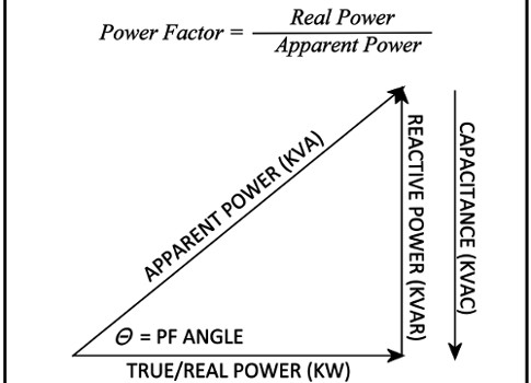
In electrical terms, low power factor appears when apparent power is much larger than active power. You can also view it as a gap between total impedance and pure resistance. In the ideal case, those reactive effects are canceled, current drops, and the supply does less non-working labor.
A simple circuit example shows this clearly. With a 230 V AC source, 60 ohms of resistance, and a 160 mH inductor, the impedance rises to about 78.25 ohms. The current is about 2.94 A, apparent power is 671 VA, active power is 515 W, and the power factor is only 0.768. The reactive part, about 431 VAR, is what creates the problem. Add a capacitor in parallel, and that reactive demand falls. The current falls too, and the power factor improves.
Power factor correction works when the load gets its reactive power nearby instead of pulling it through the whole system.
Why unity power factor is ideal, but usually not the real target
Unity power factor is the textbook goal, but most real plants don’t operate there all the time. Loads change, motors start and stop, and correction equipment switches in steps. Because of that, plants usually aim for a high practical value, often around 0.95 or higher.
That still brings big gains. As the power factor moves closer to 1.0, current drops, cable heating falls, transformer capacity opens up, and losses shrink. The point isn’t perfection. The point is better use of the electrical system you already own.
The top 3 ways to improve power factor in practice
Most industrial sites correct power factor with one of three methods. The difference between them is cost, scale, and the type of load being corrected.
Capacitor banks and APFC panels, the most common fix
Capacitors are the first choice in many plants because most industrial loads are inductive. Transformers, induction motors, and similar equipment need reactive power. Capacitors provide the opposite type, so they offset part of that lagging demand.
When a capacitor is connected in parallel with a load, reactive power is supplied near the equipment itself. That means the motor or transformer pulls less reactive power from the utility. The result is lower current and better use of the supply.
This is why capacitor banks are so common. In systems where load changes during the day, APFC panels switch capacitor steps on and off to keep the power factor near the target. In larger banks, vacuum contactor units for capacitor switching help handle the switching duty. For a broader technical reference, Eaton’s plant engineer guide to power factor correction gives a solid plant-level view.
Synchronous condenser for heavy-duty power factor correction
A synchronous condenser is a synchronous motor running at no load with overexcitation. In that state, it supplies leading reactive power back to the system. That leading reactive power offsets the lagging reactive power drawn by inductive loads.
The idea comes from how the machine builds its magnetic field. If rotor excitation is increased past the point the motor needs for itself, the excess supports the system. In effect, the machine behaves like a large adjustable capacitor. This method is useful for heavy industrial loads, but it costs more and takes more space and care than capacitor banks.
Phase advancers for large induction motors
Phase advancers are a more specialized option. They are used with large induction motors, often around 200 HP and above. Their job is to supply the motor’s excitation requirement locally, so the motor doesn’t pull as much reactive power from the line.
That makes them similar in purpose to capacitors, but narrower in use. Where a plant has large motor-driven loads and needs motor-level correction, a phase advancer can make sense.
How to choose the right power factor correction method for your system
The best method depends on load type, load size, how often demand changes, and how much cost and complexity the site can accept.
This quick comparison helps frame the choice:
| Method | Best fit | Main trade-off |
|---|---|---|
| Capacitor banks or APFC | General plant loads | Must match changing load |
| Synchronous condenser | Heavy industrial systems | Higher cost |
| Phase advancer | Large induction motors | Narrow use case |
When capacitors are enough
For many small and medium industrial systems, capacitors are enough. They are lower-cost, widely used, and easy to apply across inductive plant loads. If the site has a mix of motors and transformers and wants a practical first correction step, capacitor banks or APFC panels are often the cleanest answer.
When a heavier solution makes more sense
Bigger facilities may need more than capacitors alone. Large rotating loads, high-horsepower motor groups, or stronger correction demands can justify a synchronous condenser or phase advancer.
Before picking equipment, the plant needs real data on current, power factor, and reactive power over time. Tools for real-time monitoring of power factor and current help show whether the problem is steady, seasonal, or tied to a few large machines.
Better power factor means better use of the same system
Low power factor wastes transformer capacity, raises current, heats cables, and inflates the bill. The fix is to reduce the reactive demand seen by the supply.
Capacitor banks handle most plants well. Synchronous condensers fit heavier systems, and phase advancers suit large induction motors. When reactive power is managed near the load, the rest of the system can do the job it was bought to do.