Flip a light switch and power feels simple. Behind that simple act sits a chain of equipment that switches circuits, measures conditions, isolates faults, and keeps the rest of the system alive.
That full package is switchgear. Once that idea clicks, substations, distribution panels, and even the breaker board in a building start to make far more sense.
What switchgear really means
People often use the word switchgear as if it means only switches or breakers. In practice, the term is much wider. Switchgear includes the devices that switch a circuit, protect it during faults, measure electrical values, and support control of the system.
That matters because a power system is never a single straight line. Electricity may start at a generating station, get stepped up for long-distance transmission, pass through more than one substation, step down again for distribution, and then split across many feeders before it reaches homes, buildings, and industrial loads. Add wind, solar, and HVDC links, and the picture gets even more layered.
At every stage, someone has to connect, disconnect, protect, and monitor the circuit. That is where switchgear comes in.
A simple home circuit shows the same idea on a smaller scale. The wall switch turns a light on and off. The MCB protects the wiring during a short circuit or overload. The meter records how much electricity the site uses. A power system uses the same logic, only with much larger equipment and much higher fault levels.
IEC defines switchgear as a general term that covers switching devices and their combination with associated control, measuring, protective, and regulating equipment, along with assemblies, interconnections, accessories, enclosures, and support structures. Schneider Electric’s switchgear overview uses the same broad idea.
Switchgear is the whole fault-clearing and control package, not only the switch itself.
The devices that sit inside switchgear
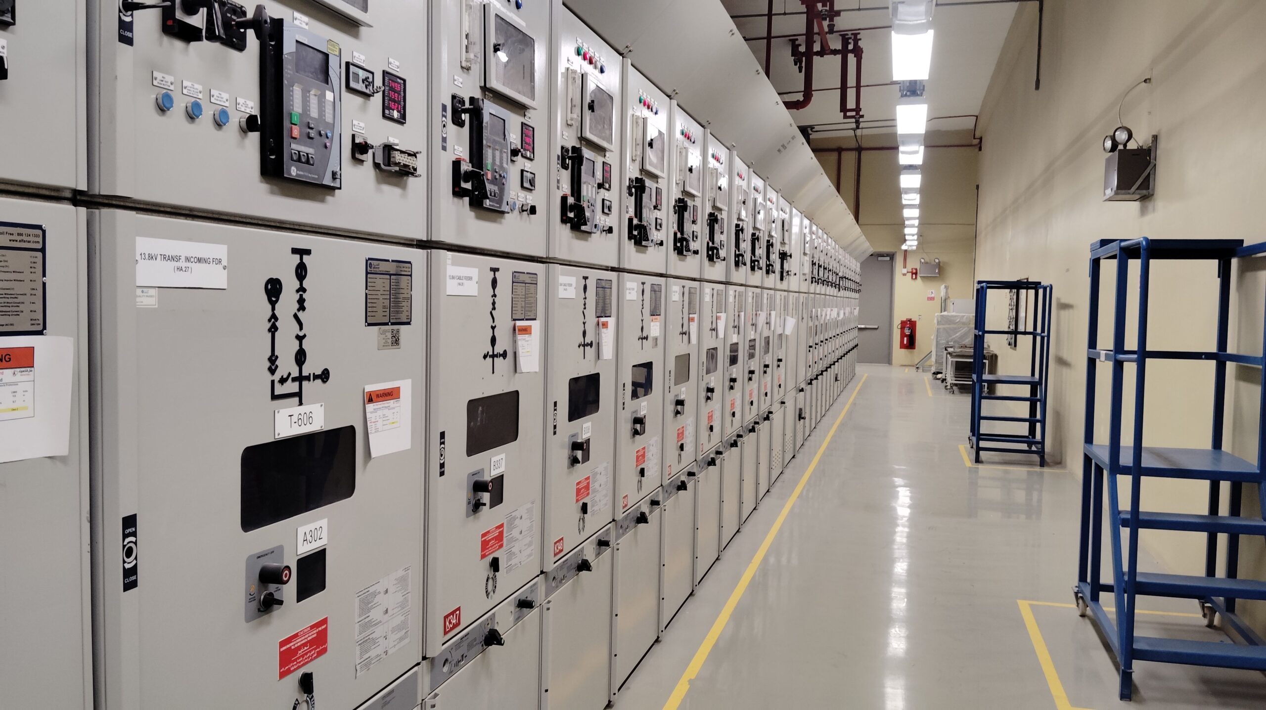
A typical switchgear lineup can include circuit breakers, switches, fuses, isolators or disconnectors, protective relays, control panels, lightning arresters, current transformers, voltage transformers, and other related parts.
Each piece has a job. The breaker opens and closes the circuit. The relay detects abnormal conditions. The current transformer and voltage transformer scale system values down to levels that measuring and protection devices can use safely.
Because of that, switchgear improves both reliability and safety. A fault can be detected and cleared fast. The damaged section can be isolated. Meanwhile, healthy sections of the system can stay energized.
How switchgear clears a fault
A circuit breaker can open during normal operation, such as maintenance or routine switching. It can also open during abnormal conditions, such as a short circuit. Still, the breaker does not “know” on its own when trouble starts.
That sensing job belongs to the relay. The relay watches system conditions and sends a trip command when it detects a fault.
Current transformers and voltage transformers make that possible. A relay cannot take direct input from transmission-level current or voltage. A current transformer reduces current to a smaller, usable value. A voltage transformer does the same for voltage. The relay reads those inputs, decides whether something is wrong, and trips the breaker if needed.
Once those parts are seen as one working set, the term switchgear stops sounding vague. It becomes a practical way to describe the control and protection layer around an electrical circuit.
The three main switchgear categories
Switchgear is commonly grouped by voltage level. That simple split helps explain where each type fits in the power system.
The breakdown below matches the standard LV, MV, and HV grouping found in many industry references, including GW Electric’s summary of switchgear types.
| Category | Typical voltage range | Common part of the system | Notes from the overview | | Low voltage (LV) | Below 1 kV | Secondary distribution, building switchboards, motor control | Often air-insulated, high current levels | | Medium voltage (MV) | 1 kV to 52 kV | Primary distribution, feeder panels, industrial distribution | Factory-assembled panels are common | | High voltage (HV/EHV) | Above 52 kV | Primary and secondary transmission, grid substations | Larger clearances, outdoor yards or compact GIS |
That voltage-based view gives a good first map. The next step is to see how each class behaves in the field.
High-voltage switchgear in transmission systems
High-voltage switchgear sits in the transmission side of the network. In IEC-based systems, anything above 52 kV falls in this group. Common rated voltages include 72.5 kV, 145 kV, 245 kV, 420 kV, and in some systems up to 800 kV, although exact ratings vary by country.
These installations appear where power leaves the generating station and enters primary transmission, and again where voltage steps down into sub-transmission. Typical rated current can reach 4,000 A, while short-circuit ratings may go up to 63 kA.
Because voltages are so high, insulation distance matters a great deal. The gap between phases, and the clearance between live parts and grounded structures, grows with the voltage rating. That is one reason high-voltage yards often look wide and open.
Air-insulated switchgear, or AIS
In high-voltage AIS, air provides the insulation between phases. That naming point matters, because the interrupter itself may still use another medium, such as SF6, inside the breaker chamber.
So, in an AIS substation, the R, Y, and B phases are separated by open air. Since air has lower dielectric strength than insulating gas, the equipment needs more physical spacing. The higher the voltage, the more distance the design requires.
That brings a few clear traits:
- AIS is usually installed outdoors.
- It needs more land than compact alternatives.
- Maintenance demands are higher because equipment sits exposed to weather and pollution.
- Cost is lower than GIS in many cases.
For that reason, AIS remains the most common high-voltage approach in many substations. Circuit breakers, disconnectors, current transformers, and other devices are often laid out as separate pieces of equipment in the yard.
Gas-insulated switchgear, or GIS
In GIS, insulating gas provides the insulation between phases. SF6 has been the most widely used gas for this job because its dielectric strength is much higher than air.
That higher strength allows designers to place parts much closer together. The result is a much more compact switchgear arrangement. A GIS installation can include the circuit breaker, current transformer, voltage transformer, disconnector, earthing switch, busbar section, cable or line connection, and local control cubicle within one metal-enclosed, factory-assembled unit.
This also changes procurement and installation. In a typical AIS yard, utilities can often source breakers, CTs, VTs, and disconnectors from different manufacturers and combine them on site. GIS is different. Because the parts are enclosed and tightly integrated, it is usually supplied as a complete assembly from one manufacturer.
That compact form makes GIS attractive where land is scarce or expensive. Urban substations often use it for that reason. Most GIS installations are indoor, although outdoor versions exist. The tradeoff is cost, because the initial investment is much higher than AIS. The market still uses SF6 heavily in this area, though SF6-free options are also being developed and applied.
Hybrid or mixed-technology switchgear
Hybrid switchgear sits between AIS and GIS. The idea is simple: combine selected GIS parts with selected AIS parts.
A common arrangement uses a dead-tank breaker with AIS disconnectors. That cuts the footprint compared with a full AIS yard, but it does not reach the compact size of full GIS.
This approach fits projects where land is tight, yet a full GIS budget is hard to justify. It is less common than AIS or GIS, but it fills a practical middle ground.
Medium-voltage switchgear in distribution networks
Medium-voltage switchgear covers the range from 1 kV to 52 kV. This is the voltage class found in primary distribution, where incoming supply is split across feeders and sent deeper into cities, plants, campuses, and large buildings. Common system levels in this space include 11 kV and 36 kV.
One key difference shows up right away. MV switchgear is usually factory-assembled in metal-enclosed panels. Instead of building an outdoor yard with separate pieces spread across wide clearances, manufacturers package the equipment inside panels that line up side by side as a switchboard.
A typical lineup includes one panel for the incomer, one for each outgoing feeder, one for the bus coupler, and sometimes a bus riser panel. Rated current often goes up to 4,000 A, and in some cases reaches 5,000 A.
For a closer look at medium voltage switchgear types, including AIS, GIS, VCB, and RMU designs, the classifications line up well with this same structure.
MV air-insulated switchgear
In medium-voltage AIS, air provides insulation between phases and between internal compartments. Because MV levels are lower than HV transmission levels, the equipment can fit inside compact metal-clad or metal-enclosed panels.
Those panels usually include a busbar compartment, cable compartment, apparatus compartment, current and voltage transformers, and a low-voltage compartment for relays and control wiring. In MV gear, the most common interruption technology is the vacuum circuit breaker, or VCB.
That combination makes MV AIS familiar in industrial plants and utility distribution rooms. It is compact enough for indoor installation, yet it still uses air as the main insulating medium.
MV gas-insulated switchgear
MV GIS follows the same compact logic as HV GIS. The difference is scale.
SF6, or another insulating gas in newer designs, allows the panel to shrink much more than air-insulated alternatives. The overview described GIS panels as being up to 75 percent smaller than comparable AIS panels at the same voltage level.
That space saving is the main draw. Cost remains the main drawback. When floor space is tight, though, GIS often wins the argument.
Shielded solid-insulated switchgear
Medium voltage also includes a less common design called shielded solid-insulated switchgear, often shortened to 2SIS.
Here, solid epoxy insulation surrounds live parts. The vacuum interrupter sits inside that insulated structure, and phase-to-phase insulation is handled by the solid material rather than air or gas. Because the live parts are covered, exposed energized surfaces are reduced.
This design can be useful in harsh sites, especially where dust, humidity, or pollution creates trouble for more open arrangements. It is not as common as AIS or GIS, but it fills a useful niche.
Low-voltage switchgear inside buildings and plants
Low-voltage switchgear covers anything below 1,000 V. This includes familiar devices such as switches, fuses, and MCBs, but in larger systems the term often points to complete LV panels and switchboards.
A good example is a residential or commercial site that receives low-voltage utility power and feeds several buildings or loads from a central room. The incoming supply does not go straight to the loads. First, it enters a low-voltage switchgear panel that can switch the circuit, protect it, meter it, and distribute it through busbars and feeders.
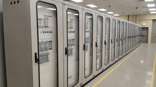
That main board may act as the site incomer or main distribution board. From there, outgoing feeders can supply different buildings, floor panels, process loads, or motor control centers.
Current levels in LV gear are high. The overview noted normal current up to 7,000 A and short-time withstand current up to 150 kA. Those numbers are large, even compared with much higher-voltage equipment. For LV assemblies, the relevant IEC family includes IEC 61439, with Part 1 covering general rules.
A closer look at low voltage switchgear solutions shows the same focus on protection, isolation, and safe distribution.
What an LV switchboard contains
Most LV switchboards are air-insulated, because the voltage is low enough that gas-insulated arrangements are far less common than in MV or HV systems. The major issue here is not extreme insulation distance. It is heat.
With thousands of amps moving through the busbar system, temperature control becomes a serious design point. Some panels rely on natural airflow. Others use forced cooling with fans to keep the internal temperature within limits.
Inside the board, common sections include:
- A control compartment with switches, relays, contactors, and small protective devices
- A busbar compartment that carries the main power path through the lineup
- An air circuit breaker compartment, because ACBs are common at this level
- A cable compartment for incoming and outgoing power cables
- A terminal block compartment for remote indication and control wiring
Layout varies by manufacturer and application, but those building blocks appear often.
Incomers, feeders, bus couplers, and motor control
LV switchboards are easier to read once the common panel roles are clear. An incomer receives supply from a transformer or utility source. A feeder sends power out to another panel or load. A bus coupler links two bus sections so one source can support the other section if needed.
That last point matters in real installations. If a site has two transformers and one fails, the bus coupler breaker can close and let the healthy transformer feed the shared load, as long as the design and loading allow it.
Motor control centers, or MCCs, often sit beside LV switchgear or are grouped with it. These are better described as control gear than pure switchgear, but the relationship is close. An MCC panel contains motor starters, contactors, MCBs, protective devices, and status indications for pumps, fans, and other motors in the system.
Once those parts are laid out on a single-line diagram, the panel room starts to read like a map. Incoming power lands at the main board, busbars carry it across the lineup, feeders split it to buildings or process loads, and MCCs handle the motor side.
Why the distinction between HV, MV, and LV matters
The voltage class tells you more than the number on the nameplate. It hints at the form of the gear, the likely breaker technology, the insulation method, the space needed, and the kind of maintenance the equipment will need.
HV gear often lives in open yards or dense GIS halls, where insulation and clearance drive the layout. MV gear usually arrives as factory-built panel lineups, often with vacuum breakers inside. LV gear packs high current into compact boards, where busbar heating, compartment design, and coordination take center stage.
Once that pattern is clear, the terms stop feeling abstract. A substation breaker yard, a medium-voltage feeder panel, and a low-voltage switchboard are all doing the same core job. They simply do it at different scales and with different design choices.
Final thoughts
Power feels simple only because switchgear does the hard work in the background. It switches circuits in normal operation, clears faults in abnormal conditions, measures what the system is doing, and isolates the damaged part before the trouble spreads.
The most useful idea to keep in mind is also the easiest to forget: switchgear is not only the breaker or the switch. It is the full set of devices and assemblies that control and protect the electrical system.
Once you know the voltage class and the insulation method, the rest starts to fall into place. Breakers, relays, CTs, busbars, feeders, and couplers stop looking like separate parts and start reading as one coordinated system.


![Voltage Sag vs Interruption: Causes, Impact, and Fixes A plant can lose a production line from a blink of power, even when the lights come back almost at once. If you've seen a VFD trip, a contactor drop out, or a PLC reset after a split-second dip, you've seen power quality turn into a production problem. The issue is often not a full outage. It's a short voltage event that sensitive equipment can't ride through. Start with the basics, and the failure starts to make sense. What voltage sag and interruption mean A voltage sag is a short drop in RMS voltage below normal, usually to 10% to 90% of rated voltage, for 0.5 cycles up to 1 minute. In a 415 V system, a brief drop to 280 V or 250 V is a sag, not a blackout. Duration matters. If voltage stays low for more than a minute, that is usually undervoltage, not sag. A sag arrives fast, recovers fast, and can still stop a machine. This quick comparison makes the difference easier to see: EventWhat happensTypical durationVoltage sagVoltage drops but does not go to zero0.5 cycles to 1 minuteVoltage interruptionVoltage is zero or near zeroLess than 1 minuteUndervoltageVoltage stays below normal for longerMore than 1 minute An interruption is more severe because supply is lost completely, or almost completely, for less than a minute. If it clears in a few seconds after auto-reclosing, it is a momentary interruption. If it stays off beyond a minute, it becomes a sustained interruption. Why these events happen The most common cause is a fault on the power system. That could be a single line-to-ground fault, line-to-line fault, double line-to-ground fault, or a three-phase fault. When fault current rises, voltage drops across the network until protection clears the problem. If the fault is on your feeder, you may see a sag first and then an interruption when the breaker opens. If the fault is on another feeder from the same substation, your breaker may never trip, but your plant can still see a bus voltage dip. That is why equipment can trip even when "our feeder never opened." Large motor starting is another frequent cause. An induction motor can draw five to seven times full-load current during start. In a weak system, or where the motor is large compared with the transformer, that inrush can create a temporary sag. Transformer energization, capacitor switching, welding loads, arc furnaces, and sudden heavy loading can do the same. Why a tiny dip can stop a large machine > The main motor may ride through a sag, but the control power often won't. Older plants had more electromechanical loads, and many of them tolerated short dips. Modern plants rely on PLCs, VFDs, servo drives, electronic power supplies, sensors, relays, and SCADA. Those devices make automation possible, but many are more sensitive to voltage dips than the motor they control. Massive steel control panels and heavy machinery dominate the floor as overhead lights cast a chaotic, flickering glow. Sharp shadows and sparks suggest a sudden surge in the facility power grid. [https://user-images.rightblogger.com/ai/f382171e-d1b1-4320-b7eb-289d9b53ee27/industrial-factory-power-instability-93e17dc7.jpg] A short sag may not stop a spinning motor because inertia keeps it moving. Still, the contactor coil can drop out, the VFD can detect undervoltage, and the PLC power supply can reset. Once the control chain breaks, the process stops. In process plants, that can mean lost batches, reset time, scrap, labor loss, and delayed delivery. Magnitude and duration both matter. Some equipment can tolerate 80% voltage for five cycles, but not 40% for the same time. That is why ride-through curves matter, and why event recording matters too. Good monitoring tools, such as monitoring power quality with PME 2024 R2 [https://www.interestingautomation.com/schneider-pme-2024-r2/], help capture minimum voltage, duration, and affected phases. Practical ways to reduce voltage sag problems The most cost-effective fix starts with the weak point. If a 200 kW machine trips because a 230 V PLC supply resets, you usually do not need to protect the whole machine. You need to protect the control power. * Specify ride-through performance when buying critical PLCs, drives, relays, and controls. * Add a small UPS, DC backup, or capacitor ride-through module for control power. * Use a voltage sag compensator or dynamic voltage restorer for sensitive process loads. * Apply online UPS systems where transfer time cannot be tolerated. * Consider motor-generator or flywheel systems where short interruptions happen often. * Use static transfer switches only when the two sources are truly independent. Source quality matters too. Utilities reduce events with better protection coordination, faster fault clearing, line maintenance, tree trimming, and feeder automation. On the plant side, grid automation and fault visibility also help, which is why tools for using Easergy T300 for fault detection [https://www.interestingautomation.com/brief-explain-easergy-t300-features-benefits-and-complete-guide/] are relevant in systems that need faster disturbance response. Final thoughts A blink in voltage can do more damage to production than a short outage, because the failure often happens inside the control system before anyone sees a breaker trip. That is the core lesson behind voltage sag and interruption studies. The best fix is rarely the biggest one. Find what actually trips, measure how deep and how long the event lasts, and protect the most sensitive part first. A brief dip should not turn into hours of downtime.](https://www.interestingautomation.com/wp-content/uploads/2026/05/Voltage-Sag-vs-Interruption-Causes-Impact-and-Fixes-150x150.jpg)


![Why MV Switchgear Fails: 5 Causes That Lead to Major Faults A 36 kV switchgear panel can sit closed for two years, carry load without complaint, and still fail on the one day you need it to clear a fault. That is the risk hiding behind a quiet panel. If the breaker won't trip, if protection doesn't detect the fault, or if insulation breaks down inside the cubicle, the result can be fire, arc flash, equipment loss, and a hard production stop. The real job is not waiting for failure and reacting later. It is spotting the warning signs before the panel runs out of margin. What counts as a switchgear failure Not every defect in a medium-voltage panel is a true failure. That distinction matters because reliability studies do not count every bad lamp, loose label, or minor nuisance the same way they count a breaker that won't trip. IEC 62271-1, clause 3.1.12, defines a major failure as a failure of switchgear and controlgear that causes the loss of one or more fundamental functions. It also says a major failure leads to an immediate change in system operating conditions, such as backup protection having to clear a fault, or forces unscheduled removal from service within 30 minutes. Major failures affect the core job of the panel In plain language, a major failure means the switchgear can no longer do one of its main jobs. Those jobs include switching, protection, monitoring, and control. If a fault occurs and the protection system does not detect it, that is a major failure. If the relay sends a trip command and the vacuum circuit breaker stays closed, that is also a major failure. The same goes for a situation where one bus section fails and the plant has to shift supply to another bus to keep running. The standard's wording about "immediate change in operating conditions" is useful because it points to real plant behavior, not theory. When primary protection fails and backup protection has to step in, the system has already moved into an abnormal state. If a breaker will not close because of a spring problem and must be removed from service at once, the equipment has lost its reliability. Minor failures are different, even if they still need attention A minor failure is anything that does not take away those core functions. An LED indication lamp that has gone dark is annoying, but it does not stop the panel from switching or protecting the system. A cosmetic defect may need correction, but it does not belong in the same category as a breaker mechanism that sticks. That distinction helps when you look at failure data. Most reliability studies focus on major failures, because those are the events that threaten safety, uptime, and equipment life. > A panel does not become dangerous only when it burns. It becomes dangerous the moment it can no longer switch, protect, or isolate a fault as intended. The five failure modes behind most serious problems Across published guidance and field experience, the same trouble spots keep showing up in MV switchgear. Insulation breakdown and mechanical faults sit near the top, while overheating, environmental stress, and aging keep chipping away at the system until something gives. A single medium voltage switchgear panel stands inside a clean and brightly lit industrial facility. [https://user-images.rightblogger.com/ai/f382171e-d1b1-4320-b7eb-289d9b53ee27/medium-voltage-switchgear-panel-dc9d5203.jpg] This quick summary helps frame where the risk usually sits: | Failure mode | Typical share or impact | Common triggers | Best early warning | | | | | | | Insulation failure | About 20% to 30% of failures | Partial discharge, insulation defects, contamination | PD testing or continuous PD monitoring | | Internal arc | Less about share, more about severity | Insulation breakdown, loose parts, human error, foreign objects | Arc detection plus proper panel design and rating | | Busbar and connection overheating | Major contributor within remaining failures | Poor joints, high contact resistance, loose terminations | Thermal inspection or continuous temperature monitoring | | Environmental and aging effects | Significant long-term driver | Moisture, dust, corrosion, seal failure, material degradation | Inspection, humidity monitoring, life assessment | | Mechanical failures | About 30% to 40% of failures | Trip coil issues, dry lubrication, worn parts, weak spring energy | Breaker monitoring and functional testing | The headline is simple. A switchgear failure usually starts as a small loss of margin, then turns into a major event when nobody is watching. Insulation failure usually starts where you can't see it Insulation failure is one of the biggest reasons MV switchgear fails. The hard part is that the panel can look healthy from the outside while the weakness grows inside cable insulation, busbar insulation, or instrument transformer resin. Partial discharge is small at first, then destructive Partial discharge starts when electrical stress concentrates inside tiny voids, impurities, or defects within insulation. In a cable, for example, a manufacturing void or a badly prepared termination can create a weak point. Stress collects there because the local dielectric strength is lower. Once the stress exceeds what that spot can withstand, a localized discharge starts. It is called "partial" because the discharge does not bridge the full insulation path at first. Still, the damage does not stay small. Repeated discharges eat away at the insulation until a much larger fault develops. A wood beam with termites offers a good comparison. The outside may still look sound, while the inside has already lost strength. By the time the damage is visible, the collapse is close. In MV panels, partial discharge often shows up in cable terminations, cable insulation itself, CT and VT epoxy insulation, and insulated busbar systems. The danger is that it rarely gives an obvious warning unless you are looking for it. For a broader research view, the review of medium-voltage switchgear fault detection [https://www.mdpi.com/1996-1073/15/18/6762] covers common detection methods and fault behavior in more detail. Periodic partial discharge testing helps, but it has a limit. You only see the panel at the moment of the test. Continuous monitoring fills the blind spot between maintenance visits. That difference matters more as the switchgear ages. Internal arc is where hidden weakness becomes immediate danger Internal arc is one of the worst events that can happen inside switchgear because it combines heat, pressure, smoke, and metal vapor in a confined space. It is not the same thing as a normal short circuit. An internal arc is a fault that develops inside the enclosure and puts people nearby at direct risk. Insulation failure can trigger it. So can a loose connection, a dropped tool, a foreign object left behind after maintenance, or simple human error. A screwdriver bridging two phases is enough to turn a routine task into a violent event. Besides fire damage, the smoke from an internal arc is hazardous on its own. That is why this topic is not only about asset protection. It is also about human safety. Modern panels may include arc detection systems that watch for both light and current. When they detect an arc, they send a trip command in milliseconds. It also pays to check whether the panel has been tested for internal arc classification, because that tells you how the equipment is expected to behave during this kind of fault. Heat at joints and contacts can undo a good panel Every electrical joint carries some risk. If the connection is poor, resistance rises. When current keeps flowing through that resistance, I squared R losses turn into heat, and heat becomes the start of the next failure. This issue appears again and again at busbar joints, cable terminations, breaker contacts, and earthing connections. The busbar connection between two panels is a common weak point. So is the cable end where termination quality depends on careful stripping, clean surfaces, correct materials, and proper tightening. In withdrawable breakers, primary contact engagement needs extra attention because poor seating can cause local hot spots. The physics is simple, but the effect is expensive. A small increase in contact resistance can push the temperature high enough to damage insulation, oxidize surfaces, weaken spring pressure, and set up the next arc fault. That is why overheating is a recurring theme in switchgear failure analysis, including this overview of switchgear failures and solutions [https://blog.exertherm.com/causes-of-switchgear-failures-and-solutions]. Good workmanship cuts most of this risk at the start. Joints need the right preparation, the right torque, and the right method from the manufacturer. After installation, thermal checks matter. A handheld IR inspection helps during rounds, but large sites with many panels often need more than occasional scans. Fixed thermal sensors on critical joints can track temperature all day and flag a problem before the panel forces a shutdown. Age and environment wear down the margin of safety Switchgear does not fail only because something was assembled badly. Time and environment also wear down the panel, even when operation looks normal. A typical service life is often described as about 25 to 30 years, though real life depends on duty, environment, maintenance, and design. Once equipment gets deep into that age range, the risk rises. Insulation can crack. Corrosion can creep across sheet metal and hardware. Seals can weaken in gas-filled compartments. Contacts wear. Springs lose strength. Materials that looked stable for years start to drift out of their original condition. Environmental stress speeds that process up. Moisture is a common problem because it lowers insulation resistance and can help contamination become conductive. Dust does the same thing when it settles where it should not. Some reported failure summaries tie a large share of busbar trouble to moisture and dust exposure, and this medium-voltage switchgear problem summary [https://www.green-energy-elec.com/common-problems-in-medium-voltage-switchgear/] highlights that pattern clearly. The fix depends on the site. Air-insulated panels in humid, dusty areas need more cleaning and inspection. Higher IP ratings help when the environment is harsh. In some applications, enclosed technologies such as GIS or solid-insulated systems reduce exposure. Humidity sensors inside selected panels also help, because they warn you when the room condition and the cubicle condition are drifting apart. Mechanical failures stop the breaker when it matters most Mechanical trouble is often the biggest single contributor to MV switchgear failure. That makes sense because a fault may be detected perfectly, yet the system still fails if the breaker mechanism cannot move. A breaker that has stayed closed for two years can look healthy, but that does not prove it will trip on demand. The trip coil may be open or shorted. Lubrication may have dried out or picked up contamination. Stored-energy springs may have weakened. Linkages may seize. Contacts may be worn. Any one of those problems can turn a valid trip command into a non-event. That is the nightmare scenario in a live plant. Fault current continues to flow because the breaker remains closed. Backup protection may clear the fault later, but the delay can mean heavier equipment damage, a wider outage, and greater risk to people nearby. Routine maintenance helps because it proves the mechanism can still move. Still, periodic checks have gaps. A breaker can pass a test in January and develop a mechanical issue in March. That is why breaker monitoring is gaining ground. Modern systems can track operating count, contact wear, gas or pressure status where relevant, opening and closing speed, and other health indicators that point to a weakening mechanism. For teams that already use connected diagnostics on breakers, tools such as a Pact series breaker diagnostic and testing interface [https://www.interestingautomation.com/schneider-electric-service-interface-kit-pact-series-circuit-breakers-installation-compatibility-expert-review/] show how live measurements and event data can shorten troubleshooting time and expose developing faults before a trip failure happens. > A breaker is not reliable because it stayed closed. It is reliable because you have evidence that it can still open. Why monitoring beats calendar-based maintenance alone Traditional maintenance still matters. Panels need cleaning, inspection, tightening, lubrication, and testing. Yet calendar-based maintenance only gives you snapshots. It cannot tell you what happened between visits. Monitoring changes that. A continuous system can watch temperature rise at a joint, catch partial discharge activity, track humidity inside a cubicle, and record breaker operation data around the clock. It also makes condition-based maintenance possible. Instead of opening equipment on a fixed calendar, you act when data shows the condition is changing. That approach is often the difference between "repair after failure" and "intervene before failure." On new switchgear, you may not need every sensor from day one. On older panels, on hard-worked breakers, or across a large fleet, the case for monitoring becomes much stronger. A plant-wide supervision layer also helps because raw data is not enough by itself. Operators need one place to see alarms, status changes, and events in context. Platforms focused on real-time monitoring with Schneider EPAS [https://www.interestingautomation.com/schneider-electric-epas/] show why visibility matters when a feeder trips or a breaker changes state. Faster fault isolation starts with seeing the right information at the right time. Final thoughts The most dangerous switchgear failures do not start with a dramatic event. They start with a missed warning, a weak joint, a dry mechanism, or insulation that is breaking down in silence. If there is one takeaway to keep, it is this: reliability needs proof. A breaker that has been closed for two years is only comforting when you know it can still trip today, and the rest of the panel can still do its core job when the fault arrives.](https://www.interestingautomation.com/wp-content/uploads/2026/05/Why-MV-Switchgear-Fails-5-Causes-That-Lead-to-Major-Faults-150x150.jpg)