A premium circuit breaker won’t save a switchgear panel if the low-voltage compartment is poorly wired, badly understood, or not working right. This small section controls the logic, status, alarms, and protection that tell the rest of the panel what to do.
If you work around switchgear, this is the compartment you can’t afford to ignore. Once you understand what lives inside it, the whole panel starts to make more sense.
Why it’s called a low-voltage compartment
The name can sound strange at first. After all, you might be looking at a 36 kV medium-voltage panel, or even a much larger high-voltage installation. The cable compartment is at system voltage. The circuit breaker chamber is at system voltage. The busbar compartment is at system voltage. Then one compartment breaks that pattern.
That compartment runs on low control voltages, often 110 V DC, 220 V DC, or 48 V DC. Because of that, it is called the low-voltage compartment, or LV box. In many panels, people also call it the metering and relay chamber.
The reason is simple. Devices like meters, relays, indication lamps, annunciators, and selector switches are not built to work directly at 36 kV. If they were, they would be large, expensive, and impractical to place on a normal panel door. So the switchgear uses instrument transformers to bring those values down to something usable.
A current transformer, or CT, reduces primary current to a secondary value such as 1 A. A voltage transformer, often called a VT or PT, reduces primary voltage to a much lower value such as 110 V divided by root 3 or 220 V divided by root 3. Those stepped-down signals then feed the meters and protection devices inside the LV box.
The LV box may sit inside a 36 kV panel, but it does not run on 36 kV. It runs on low-voltage control power and low-level measurement signals.
If you want wider context on panel types, breaker arrangements, and where this compartment fits into the whole assembly, this guide to medium-voltage switchgear types is a helpful companion.
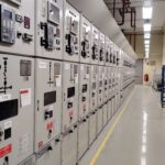
Where the LV box sits in a switchgear panel
In most low-voltage and medium-voltage switchgear, the LV compartment is placed where operators can reach it easily. That often means at the top of the panel, above the breaker or busbar sections. This position makes sense because the door usually carries the devices that people need to read or operate during normal service.
Ring Main Units, or RMUs, often place their low-voltage devices in a top-mounted section as well. On gas-insulated high-voltage equipment, the same idea still appears, although the layout can look different. In those cases, the compartment may include HMIs along with status points and control devices.
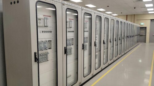
Still, there is no single layout that every manufacturer follows. Some panels have the full LV box at the top. Others split the arrangement, with part of the compartment at the top and part at the bottom. The design changes with the project, the customer, the protection scheme, and the builder’s own panel architecture.
That last point matters. There is no fixed rule that says every low-voltage compartment must contain the same devices in the same order. Two projects from the same company can end up with different LV boxes if the protection logic, metering needs, or operational interlocks change.
So while the location is often easy to spot, the exact content is never guaranteed. One panel may have a simple relay, a few lamps, and a couple of selector switches. Another may have dense wiring, multiple relays, extra annunciation, communication hardware, and a more complex HMI setup.
What powers the LV box
Three inputs matter most inside a low-voltage compartment: auxiliary supply, CT input, and VT/PT input.
The first is the auxiliary power supply. This is what powers the control and indication side of the panel. Depending on the project, that may be 110 V DC, 220 V DC, or 48 V DC. On site, this supply may come from a battery bank. In other cases, an auxiliary transformer steps the voltage down and a DC source is derived from it for control use. Lamps, relays, selector switches, hooters, and trip circuits depend on that supply.
Many engineers first notice how often DC appears in these panels. If you want a separate explanation of that choice, this short video on why DC supply is used in the LV box adds useful background.
The second input comes from the current transformer. A panel may carry hundreds of amps on the primary side, but the measuring and protection devices in the LV section only see the stepped-down secondary current. For example, an 800 A primary value might be reduced to 1 A on the secondary side. That smaller signal is what feeds an ammeter or protection relay.
The third input comes from the voltage transformer. A 36 kV system voltage cannot go straight into a voltmeter or relay. The VT reduces it to a usable secondary value and sends that signal to metering and voltage-based protection functions.
If you want a broader manufacturer reference on the subject, Eaton’s fundamentals of medium-voltage switchgear gives a solid high-level overview.
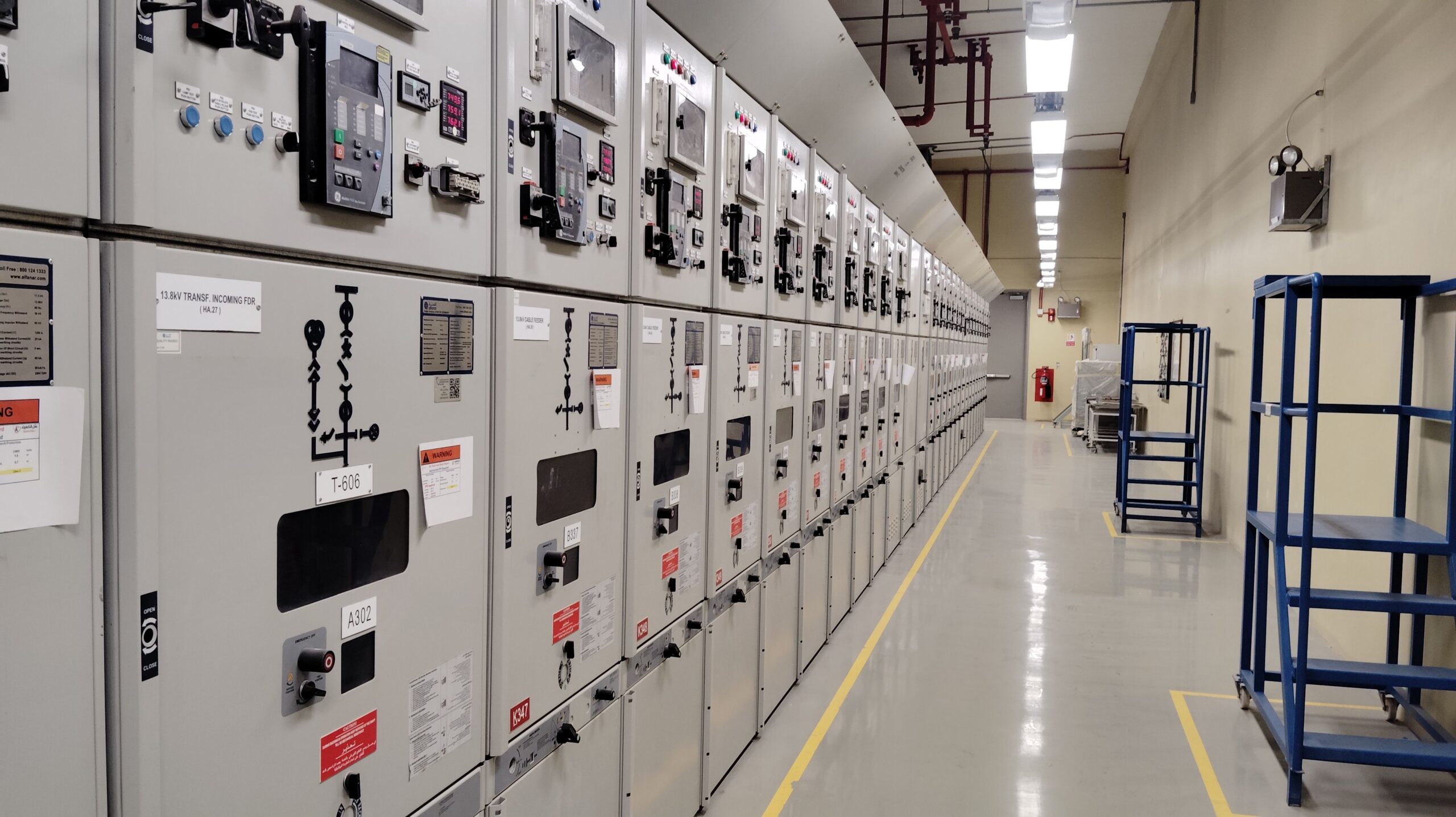
The main devices you will find inside the LV compartment
The LV box is where the panel starts talking back to you. It shows status, reports trouble, accepts commands, and runs protection logic. Although designs vary, a handful of devices appear again and again.
Indication lamps show normal operating status
Indication lamps are small, but they carry a lot of meaning. A glance at the panel door can tell you whether the breaker is on, off, or tripped. You may also see a lamp for spring-charged status, breaker-in-service position, or trip-circuit healthy condition.
These lamps work through low-voltage control logic, not primary voltage. For breaker-related indications, the panel often uses the breaker auxiliary switch. As the breaker changes position, those auxiliary contacts change state too. That change then energizes the relevant lamp through the control circuit.
A good lamp layout makes routine operation much easier because you do not need to open compartments or guess at device position.
Annunciators point to abnormal conditions
Annunciators are different from ordinary status lamps. They are there to flag faults and abnormal conditions. Typical windows may indicate overcurrent trip, earth fault, phase-to-ground fault, or an unhealthy circuit.
This distinction helps:
| Device | Main purpose | Common examples |
|---|---|---|
| Indication lamps | Show operating status | Breaker ON/OFF, spring charged, trip circuit healthy |
| Annunciators | Show fault or alarm conditions | Overcurrent trip, earth fault, abnormal circuit condition |
When a fault occurs, the related annunciator window may blink. In many panels, a hooter sounds at the same time. If the annunciator unit does not include its own audible signal, the panel may use a separate electronic hooter.
That sound matters in a substation or switch room because it helps staff locate the affected panel fast.
Meters turn electrical values into readable information
Meters are another common part of the LV compartment. Some panels use dedicated analog or digital ammeters and voltmeters. Others use a multifunction meter, which packs several readings into one device.
A multifunction meter may show current, voltage, power factor, active power, and reactive power. Some panels also include revenue metering, depending on the application. That means the switchgear is not only controlling the feeder, it is also tracking electrical consumption in a billing-grade or monitoring role.
The exact meter choice depends on the job. A simple feeder may need only the basics. A more data-heavy panel may call for multifunction metering and communication outputs.
Selector switches let operators choose how the panel behaves
Selector switches are some of the most hands-on devices in the LV box. One of the most common is the local/remote switch. When the switch is in remote, the panel accepts commands from SCADA or another control system. When it is in local, panel-side operation is allowed and remote control is blocked.
That does more than change convenience. It also works as an interlock. If someone is standing at the panel for local operation, you do not want a second operator sending a remote command at the same time.
Another common switch is the TNC switch, which means trip, neutral, and close. Turn it to trip, and the breaker trips. Leave it at neutral, and the breaker stays in its present state. Turn it to close, and the breaker closes, assuming all interlocks allow it.
Similar selector arrangements can also appear for disconnectors and earthing switches.
Protective relays are the logic center inside the logic center
If the LV box is the brain of switchgear, the relay is one of its sharpest parts. Modern protective relays can combine many functions in one unit. A single relay may handle overcurrent, earth fault, sensitive earth fault, phase imbalance, thermal overload, breaker failure, condition monitoring, and trip-circuit failure.
Some panels use one multifunction relay. Others use several relays depending on the scheme. In more advanced setups, the relay may also communicate with SCADA, record events, and support deeper diagnostics.
In one common panel style, the relay is withdrawable. That means maintenance staff can remove and replace it more easily if needed, much like a draw-out component.
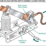
VDIS adds a layer of safety on medium-voltage gear
Voltage Detection and Indication System, or VDIS, appears often on RMUs and medium-voltage switchgear. Its job is simple but important: it indicates whether voltage is present on the line side.
Before maintenance begins in a cable compartment, VDIS helps confirm whether voltage is still present.
That matters because maintenance on a live cable side is dangerous. The indication gives staff one more check before work starts. In practice, VDIS is far more common on RMUs and MV gear than on large high-voltage or extra-high-voltage switchgear.
Modern compact switchgear keeps adding smarter interfaces and monitoring features as well. That broader shift shows up in these future trends in electrical switchgear technology, especially where HMIs and digital supervision are becoming more common.
A simple LV box layout, piece by piece
A basic low-voltage compartment can tell you a lot about how a panel is meant to be used.
At the top, you may find status indications such as breaker ON, breaker OFF, breaker trip, and spring charged. Those are quick checks. An operator standing in front of the panel can understand the breaker state in seconds.
Below that, a multifunction meter may sit in the center of the door. From one screen, it can show current, voltage, power factor, active power, and reactive power. Nearby, a withdrawable relay may hold the feeder protection settings and trip logic.
An annunciator block often sits next to those devices. In one simple arrangement, two windows may be assigned to overcurrent trip and earth fault trip, while two more remain spare for future use. Beside it, an electronic hooter gives an audible alarm when one of those faults appears.
The lower section usually carries the control hardware. One selector switch handles local and remote operation. Another works as the TNC switch. A reset push button often acts as a master reset for annunciation or fault indications after the cause has been cleared.
Open the compartment and the neat front-door layout gives way to something else. You see a dense field of wires, terminal blocks, logic paths, MCBs, and sometimes contactors. That complexity grows fast. Add more protection functions, and you need more logic. Add more logic, and you need more wiring, more interlocks, and more cost.
That is why two LV boxes rarely look the same inside, even when they look similar from the front.
Why this small compartment matters so much
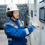
The low-voltage compartment gets more attention from operators than the breaker chamber or cable chamber. It is the part designed for normal interaction during service. Staff read indications there, check metering there, acknowledge alarms there, and issue control commands there.
Because of that, the LV box has an outsized effect on how safe and usable the panel feels. A panel with strong primary hardware but weak control wiring can still become a headache. The breaker may be expensive. The busbar may be well built. Yet if the protection relay is misconfigured, the selector logic is wrong, or the annunciation is unclear, the panel will not behave the way it should.
That is why calling the LV box the “brain” of switchgear is not an exaggeration. It is where measurement, control, interlocking, alarm handling, and protection meet in one place.
For readers who want to keep building from this topic into a wider study path, the medium-voltage switchgear playlist is a useful next step.
What to remember about the LV box
The low-voltage compartment may occupy only a small part of the panel, but it controls how the whole switchgear assembly thinks, reacts, and communicates. That is why a fault there can stop a panel from operating properly, even when the main breaker hardware is in good shape.
If you understand the LV box, you understand where status signals come from, how trips are issued, how measurements are taken, and how operators interact with live equipment from a safer interface. In switchgear, that small compartment often explains the whole system.

![Voltage Sag vs Interruption: Causes, Impact, and Fixes A plant can lose a production line from a blink of power, even when the lights come back almost at once. If you've seen a VFD trip, a contactor drop out, or a PLC reset after a split-second dip, you've seen power quality turn into a production problem. The issue is often not a full outage. It's a short voltage event that sensitive equipment can't ride through. Start with the basics, and the failure starts to make sense. What voltage sag and interruption mean A voltage sag is a short drop in RMS voltage below normal, usually to 10% to 90% of rated voltage, for 0.5 cycles up to 1 minute. In a 415 V system, a brief drop to 280 V or 250 V is a sag, not a blackout. Duration matters. If voltage stays low for more than a minute, that is usually undervoltage, not sag. A sag arrives fast, recovers fast, and can still stop a machine. This quick comparison makes the difference easier to see: EventWhat happensTypical durationVoltage sagVoltage drops but does not go to zero0.5 cycles to 1 minuteVoltage interruptionVoltage is zero or near zeroLess than 1 minuteUndervoltageVoltage stays below normal for longerMore than 1 minute An interruption is more severe because supply is lost completely, or almost completely, for less than a minute. If it clears in a few seconds after auto-reclosing, it is a momentary interruption. If it stays off beyond a minute, it becomes a sustained interruption. Why these events happen The most common cause is a fault on the power system. That could be a single line-to-ground fault, line-to-line fault, double line-to-ground fault, or a three-phase fault. When fault current rises, voltage drops across the network until protection clears the problem. If the fault is on your feeder, you may see a sag first and then an interruption when the breaker opens. If the fault is on another feeder from the same substation, your breaker may never trip, but your plant can still see a bus voltage dip. That is why equipment can trip even when "our feeder never opened." Large motor starting is another frequent cause. An induction motor can draw five to seven times full-load current during start. In a weak system, or where the motor is large compared with the transformer, that inrush can create a temporary sag. Transformer energization, capacitor switching, welding loads, arc furnaces, and sudden heavy loading can do the same. Why a tiny dip can stop a large machine > The main motor may ride through a sag, but the control power often won't. Older plants had more electromechanical loads, and many of them tolerated short dips. Modern plants rely on PLCs, VFDs, servo drives, electronic power supplies, sensors, relays, and SCADA. Those devices make automation possible, but many are more sensitive to voltage dips than the motor they control. Massive steel control panels and heavy machinery dominate the floor as overhead lights cast a chaotic, flickering glow. Sharp shadows and sparks suggest a sudden surge in the facility power grid. [https://user-images.rightblogger.com/ai/f382171e-d1b1-4320-b7eb-289d9b53ee27/industrial-factory-power-instability-93e17dc7.jpg] A short sag may not stop a spinning motor because inertia keeps it moving. Still, the contactor coil can drop out, the VFD can detect undervoltage, and the PLC power supply can reset. Once the control chain breaks, the process stops. In process plants, that can mean lost batches, reset time, scrap, labor loss, and delayed delivery. Magnitude and duration both matter. Some equipment can tolerate 80% voltage for five cycles, but not 40% for the same time. That is why ride-through curves matter, and why event recording matters too. Good monitoring tools, such as monitoring power quality with PME 2024 R2 [https://www.interestingautomation.com/schneider-pme-2024-r2/], help capture minimum voltage, duration, and affected phases. Practical ways to reduce voltage sag problems The most cost-effective fix starts with the weak point. If a 200 kW machine trips because a 230 V PLC supply resets, you usually do not need to protect the whole machine. You need to protect the control power. * Specify ride-through performance when buying critical PLCs, drives, relays, and controls. * Add a small UPS, DC backup, or capacitor ride-through module for control power. * Use a voltage sag compensator or dynamic voltage restorer for sensitive process loads. * Apply online UPS systems where transfer time cannot be tolerated. * Consider motor-generator or flywheel systems where short interruptions happen often. * Use static transfer switches only when the two sources are truly independent. Source quality matters too. Utilities reduce events with better protection coordination, faster fault clearing, line maintenance, tree trimming, and feeder automation. On the plant side, grid automation and fault visibility also help, which is why tools for using Easergy T300 for fault detection [https://www.interestingautomation.com/brief-explain-easergy-t300-features-benefits-and-complete-guide/] are relevant in systems that need faster disturbance response. Final thoughts A blink in voltage can do more damage to production than a short outage, because the failure often happens inside the control system before anyone sees a breaker trip. That is the core lesson behind voltage sag and interruption studies. The best fix is rarely the biggest one. Find what actually trips, measure how deep and how long the event lasts, and protect the most sensitive part first. A brief dip should not turn into hours of downtime.](https://www.interestingautomation.com/wp-content/uploads/2026/05/Voltage-Sag-vs-Interruption-Causes-Impact-and-Fixes-150x150.jpg)