Harmonics are one of those power-quality problems that can stay invisible until they start causing real headaches, hot cables, nuisance trips, or sensitive equipment acting strangely. The good news is that on Schneider Electric Altivar Process drives (ATV600 and ATV900), you can get very low THDi by adding an upstream passive filter and enabling the drive’s Input Filter (iFi) function so everything stays stable.
What harmonics look like on a VFD input (and why they matter)
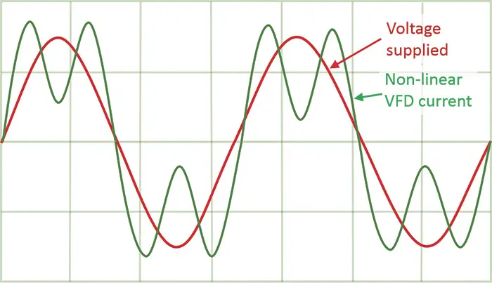
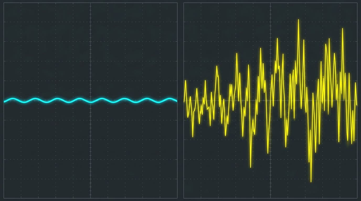
 An oscilloscope-style comparison of distorted current without a filter versus a cleaner waveform with a passive filter.
A variable frequency drive (VFD) does not draw a perfectly smooth sine-wave current from the supply. Because the drive front end rectifies AC to DC, it pulls current in pulses. Those pulses create harmonic currents on the mains supply. In plain terms, the drive “sips” power in uneven gulps instead of a steady drink, and the electrical system feels it.
Those harmonics can have negative effects on an installation, especially as more drives are added or when the source impedance is not ideal. Even when everything “works,” harmonic currents can increase heating and distortion on the supply.
Schneider Electric Altivar Process drives mitigate harmonics with an embedded low-harmonic DC choke. In the demonstrated setup, the drive on its own achieves a total harmonic distortion of input current (THDi) of less than or equal to 48% thanks to that built-in choke. That built-in reduction helps, but many sites want much lower THDi to meet internal standards or utility requirements.
To see the real impact, measurements were taken at consistent points:
- Input current
- DC bus voltage after the rectifier
- Output current
With the drive running at 50 Hz and a 30 kW motor at nominal load (no passive filter installed), THDi measured about 40%. That number is not unusual for a 6-pulse rectifier front end, and it explains why passive filters are a common add-on when power-quality limits are tighter.
If you want a quick refresher on how drive reactors and chokes help reduce harmonics and protect equipment, this overview on VFD chokes for harmonic mitigation provides helpful background.
Picking the right passive filter (and the site conditions that matter)
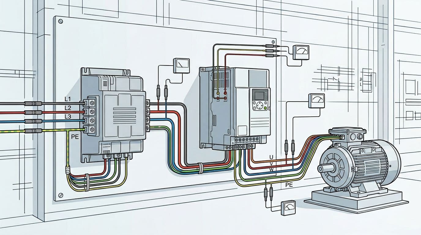 An example layout showing mains to passive filter to drive to motor, with measurement points for current and DC bus voltage.
Passive filters reduce the consequences of harmonics by shaping the input current so it looks more like a sine wave. In this demonstration, the setup used:
- Drive: ATV630 D30N4
- Passive filter: 5% passive filter VW3A46127
- Motor: 30 kW, nominal load
Passive filters are typically selected to limit THDi to 10% or even 5% at the current rating, but selection is not just “pick one that fits the amps.” The filter must be selected according to the drive, and Schneider points users to the product catalog for that selection process (see the Altivar Process ATV900 catalog).
One key detail in the video is the condition attached to the THDi performance claims: the THDi value is defined for a short-circuit ratio Rce greater than or equal to 66%. Rce defines the line impedance at the passive filter connection point. In other words, the available short-circuit level and upstream impedance matter. If the source is “soft” (higher impedance), performance can shift.
Upstream protection is also part of the selection. The guidance is to choose protection devices based on the catalog data. There’s also an important warning: if a passive filter option is required, the minimum prospective short-circuit current capability of the source is reduced at the drive connection point. You must estimate it using the impedance values from the installation manual. For drive-side installation details, Schneider provides the ATV630-650 installation manual.
For a Schneider-written summary of what passive filters do (including the “reactive power at low load” behavior), see passive filter functions for ATV600 drives.
If you’re evaluating a passive filter for compliance, don’t skip the Rce condition. The source impedance at the connection point is part of the result, not a footnote.
Wiring a passive filter upstream: shunt vs capacitor contactor
Passive filters in this family connect upstream of the drive. Once installed, the same measurement points can be used to compare results (input current, DC bus voltage after rectifier, and output current).
Schneider provides installation guidance for ATV passive filters in an instruction sheet (see ATV passive filter instruction sheet VW3A46101 to A46176).
Default “shunt” configuration and standby reactive current
Out of the box, the passive filter is configured with a shunt, which means the internal capacitors of the filter are always in use.
With the filter connected in its default setup and the drive in a ready (standby) state, you can observe reactive current at the input even when not running. In the demonstration, that standby current is about 25% of nominal current.
This is not a wiring mistake. It’s a behavior tied to capacitors being connected.
Using a capacitor contactor to remove reactive current in standby
To remove that reactive current in standby mode, Schneider shows using a contactor to disconnect the filter capacitors. In the wiring approach shown, the contactor replaces the short-circuit wires between X3 and X4 terminals.
Schneider also notes a practical operational point: using a capacitor contactor is recommended. Without a capacitor contactor, you must adapt the wiring diagram to wait 25 seconds after opening (to allow discharge and a safe return to ready state behavior).
When returning to a ready state with open contactors, the setup clearly shows no input current in standby. That’s the payoff of controlling the capacitive portion.
If you’re coordinating optional contact behavior with Process Drives, Schneider also documents related considerations in passive filter optional contacts guidance.
Drive programming: enabling the iFi (Input Filter) function
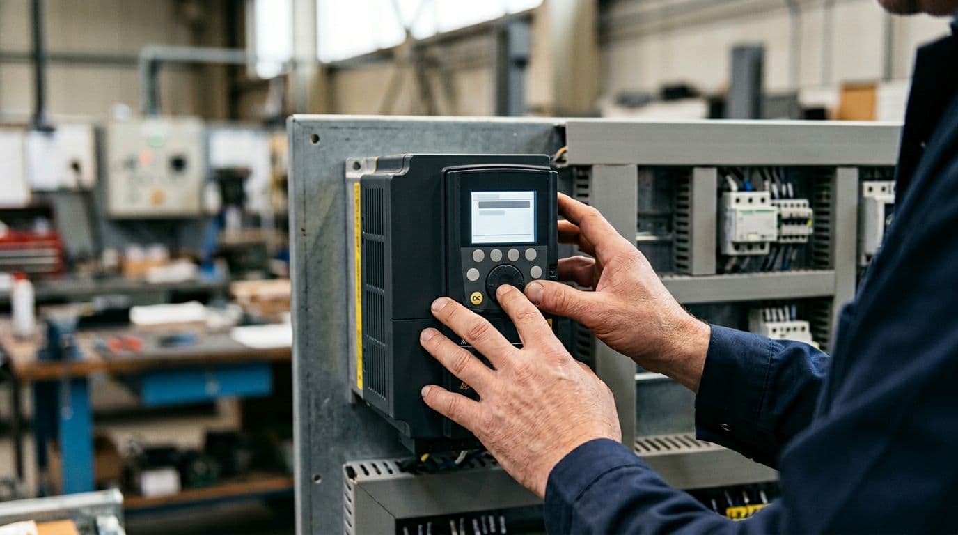 Adjusting drive parameters at the keypad to enable the input filter function.
A passive filter is not just a bolt-on component. The drive needs to know it’s there, because the filter changes the input dynamics. That’s where the Input Filter (iFi) setting comes in.
Why “Input filter = Yes” might not be selectable at first
Before using an input passive filter, you must set Input filter.
In the drive menu, the path shown is:
- Complete settings
- Motor parameters
- Input filter
However, the video shows an easy-to-miss detail: sometimes you can only choose No for the input filter setting. That happens because the U/F motor control law for asynchronous motors must be selected for the function to be available.
To activate the function:
- Go to Motor control type
- Select U/F VC standard or U/F BC 5 points
- Then set Input filter to Yes
That sequence matters because it prevents a common “why is the option missing?” moment during commissioning.
DC bus ripple monitoring and relay setup (R2)
With a contactor involved, the drive also needs to monitor the DC bus behavior appropriately. The video references DC bus ripple config, which monitors the DC bus voltage for connection with the contactor.
A relay configuration example is also shown:
- Press F4 to set the relay
- Go to R2 configuration
- Set R2 assignment to Drive running
That’s a practical way to coordinate control logic so the contactor behavior matches drive state, especially in systems where you want the capacitors disconnected when the drive is idle.
For additional context from Schneider on this same topic, see their support page: harmonics reduction video and iFi notes.
Results: THDi drops from about 40% to about 4.2%
With the passive filter installed and configured, the drive was run again at 50 Hz with the same 30 kW motor at nominal load.
The measured outcome:
- THDi reduced to 4.2%
That change is large enough to see immediately on the waveform. The input current becomes much cleaner, which is the whole point of installing the passive filter in the first place.
At this stage, it’s tempting to declare victory and move on. Still, the next part is the one that saves time later: making sure the drive’s input filter setting stays correct, because a wrong parameter can cause unstable behavior even if the wiring is perfect.
Why the iFi parameter matters: avoiding DC bus oscillations
 Stable DC bus ripple versus unstable oscillation when the filter setting is wrong.
The video makes a clear point: if the drive is not properly set up with a filter, it may encounter DC bus oscillations at certain speeds or load ranges.
What “normal” DC bus ripple looks like
In normal conditions (with correct configuration), the DC bus ripple is shown as under 30 volts, regardless of the load. That gives a baseline for what stable behavior looks like.
What happens when Input filter (iFi) is set to No with a passive filter installed
To show the impact, the drive’s input filter setting is changed to No while the passive filter remains installed.
There’s another gotcha here: when you change input filter from Yes to No, the DC bus ripple config is set by default to Ignore. In the demonstration, it’s changed manually to Error so the drive can report the issue and the oscillation is easier to illustrate.
To trigger a problem state, the test runs at:
- 46 Hz
- Nominal load
Schneider notes that this phenomenon can occur at other set points too, depending on motor frequency, switching frequency, and load. After reaching nominal motor load, the DC bus voltage shows strong oscillations, up to 193 VDC of ripple in the example.
As the DC bus becomes unstable, THDi also goes out of range because the input current becomes unstable. After a few operating cycles, the drive detects a DC bus ripple error.
Installing the passive filter is only half the job. If the drive’s iFi setting doesn’t match the hardware, DC bus ripple can spike and the input current can become unstable.
Restoring stable operation by enabling iFi
When the input filter function is switched back to Yes, operation returns to normal behavior. THDi comes back in line with the passive filter specification, and DC bus behavior stabilizes.
If you’ve ever dealt with drive component stress, you already know why this matters. Excess electrical stress can contribute to failures over time. For a broader look at drive DC bus capacitor failure modes, this guide on causes of VFD capacitor failure is a useful companion read.
Conclusion: clean harmonics need both hardware and the right parameter
A passive filter installed upstream of an Altivar Process drive can cut THDi dramatically (from about 40% down to about 4.2% in the demonstrated 30 kW setup). Still, the real win comes when the drive configuration matches the hardware. Set the control type so the input filter option is available, then enable iFi, and configure DC bus ripple handling so the system stays stable.
If you’re chasing low THDi numbers, remember this simple idea: the filter cleans up the input waveform, but iFi keeps the DC bus from misbehaving across different speeds and loads.