Table of Contents
- Introduction
- Understanding Solar Power Plants
- 2.1 Basics of Solar Energy Generation
- 2.2 The Role of Inverters in Solar Power Plants
- 2.3 Why Transformers are Needed in Solar Applications
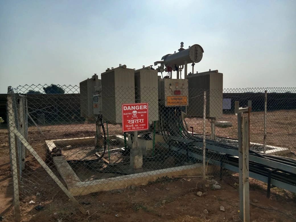
- What is an Inverter Duty Transformer (IDT)?
- 3.1 Definition
- 3.2 Difference Between Conventional Transformer and IDT
- 3.3 Construction Features of IDT
- Technical Reasons for Using IDT in Solar Plants
- 4.1 Harmonics Handling
- 4.2 Insulation Stress Management
- 4.3 Higher Frequency Withstand Capability
- 4.4 Thermal Performance in Harsh Solar Environments
- 4.5 Protection Against DC Injection
- Working Principle of IDT in Solar Plants
- 5.1 Power Flow in a Solar Plant (From PV Panels to Grid)
- 5.2 Where IDT Fits in the System
- 5.3 Step-up Functionality Explained
- Design Considerations for IDT in Solar Plants
- 6.1 Copper vs Aluminum Windings
- 6.2 Core Materials and Design
- 6.3 Cooling Methods (ONAN, ONAF, etc.)
- 6.4 Loss Minimization and Efficiency Standards
- 6.5 Insulation Class and Thermal Rating
- Advantages of Using IDT in Solar Power Plants
- 7.1 Improved Reliability
- 7.2 Longer Service Life
- 7.3 Grid Compliance
- 7.4 Enhanced Power Quality
- 7.5 Economic Benefits Over the Long Term
- Challenges and Limitations of IDT
- 8.1 Higher Cost Compared to Conventional Transformers
- 8.2 Maintenance Concerns
- 8.3 Requirement for Specialized Design
- Comparison: Inverter Duty Transformer vs Conventional Transformer
- 9.1 Performance Parameters
- 9.2 Harmonic Tolerance
- 9.3 Efficiency Differences
- 9.4 Grid Integration Capability
- 9.5 Case Example
- Applications Beyond Solar Power
- 10.1 Wind Energy Systems
- 10.2 Battery Energy Storage Systems (BESS)
- 10.3 Hybrid Renewable Plants
- Future Trends of Inverter Duty Transformers
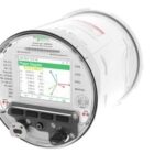
- 11.1 Digital Monitoring & Smart Transformers
- 11.2 Green Transformers with Eco-Friendly Fluids
- 11.3 Integration with IoT and SCADA Systems
- Case Studies of IDT in Real Solar Projects
- 12.1 Utility-Scale Solar Plant Example
- 12.2 Rooftop Solar with IDT Application
- 12.3 Microgrid and Off-grid Case
“Why IDT (Inverter Duty Transformer) is used in Solar Plants – Learn the importance, working, advantages, and future trends of IDTs in solar power generation with complete explanation.”
1. Introduction
👉 “Why IDT (Inverter Duty Transformer) is used in Solar Plants”
The world is shifting towards renewable energy at an unprecedented pace. Among the various sources of clean energy, solar power has emerged as the fastest-growing sector. Solar photovoltaic (PV) plants have been installed globally at utility, commercial, and residential scales. However, generating electricity from solar panels is not as simple as it seems.
One crucial component that ensures the integration of solar energy with the grid is the Inverter Duty Transformer (IDT). While the average person might only see solar panels and inverters, engineers know that IDTs play a silent yet critical role in making sure that the power generated is reliable, stable, and compatible with the utility grid.
In this article, we will explore why IDTs are used in solar plants, their construction, working, advantages, and future trends, along with real-world examples.
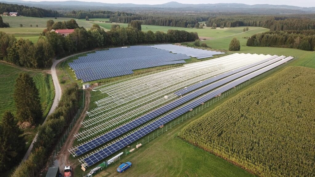
2. Understanding Solar Power Plants
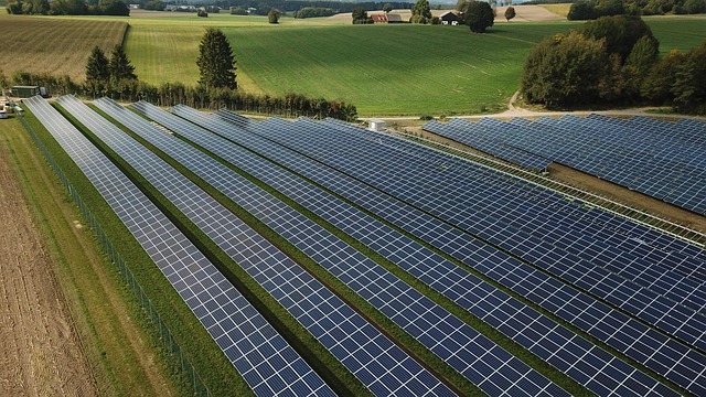
2.1 Basics of Solar Energy Generation
Solar photovoltaic modules convert sunlight directly into direct current (DC). Since our utility grids and most household appliances run on alternating current (AC), the generated DC must be converted to AC before use.
2.2 The Role of Inverters in Solar Power Plants
Inverters are the heart of any solar power plant. They:
- Convert DC from panels into AC.
- Synchronize AC output with the grid.
- Control voltage, frequency, and reactive power.
- Manage system safety through protection mechanisms.
2.3 Why Transformers are Needed in Solar Applications
The electricity generated by solar inverters is usually low to medium voltage (400V – 33kV). However, transmission lines and utility grids typically operate at much higher voltages (66kV – 765kV).
Hence, transformers are required to step up the voltage to grid levels. But unlike conventional power generation, solar introduces unique challenges such as harmonics, voltage fluctuations, and rapid load changes.
This is where Inverter Duty Transformers come into play.
3. What is an Inverter Duty Transformer (IDT)?
3.1 Definition
An Inverter Duty Transformer (IDT) is a specially designed transformer that connects solar inverters to the grid, handling the unique electrical stresses produced by inverters such as harmonics, switching surges, and high-frequency components.
3.2 Difference Between Conventional Transformer and IDT
A conventional transformer is designed for clean sinusoidal waveforms. In contrast, an IDT is designed to withstand non-sinusoidal waveforms, harmonics, and higher thermal stress.
Key Differences:
- Higher insulation levels in IDT.
- Special core design to minimize harmonic losses.
- Better cooling arrangements.
- Enhanced thermal capacity.
3.3 Construction Features of IDT
- Electrostatic shielding to block harmonic distortions.
- Reinforced insulation to withstand voltage spikes.
- Amorphous or CRGO steel cores to minimize core losses.
- ONAN or ONAF cooling for reliability in hot climates.
4. Technical Reasons for Using IDT in Solar Plants
4.1 Harmonics Handling
Solar inverters produce current harmonics due to high-frequency switching. IDTs are designed to absorb these harmonics without excessive heating or distortion.
4.2 Insulation Stress Management
Fast switching from IGBTs in inverters generates voltage transients. IDTs have stronger insulation systems to protect against these stresses.
4.3 Higher Frequency Withstand Capability
Unlike grid electricity (50/60Hz), inverter output contains frequencies up to several kilohertz. IDTs are tested for such high-frequency components.
4.4 Thermal Performance in Harsh Solar Environments
Solar plants are often located in deserts or tropical climates. IDTs have:
- High thermal endurance.
- Cooling ducts and oil circulation.
- Capability to withstand cyclic loading.
4.5 Protection Against DC Injection
Inverter faults can inject DC components into transformers. IDTs prevent saturation and damage by design.
5. Working Principle of IDT in Solar Plants
5.1 Power Flow in a Solar Plant (From PV Panels to Grid)
- PV modules generate DC.
- Inverters convert DC → AC.
- AC passes through IDT.
- IDT steps up voltage for transmission.
5.2 Where IDT Fits in the System
IDT is placed between the solar inverter output and the grid interconnection point.
5.3 Step-up Functionality Explained
Example:
- Inverter output = 690V AC.
- Grid requirement = 33kV AC.
- IDT steps up 690V → 33kV efficiently.
6. Design Considerations for IDT in Solar Plants
- Copper vs Aluminum Windings: Copper offers higher efficiency, aluminum is cheaper.
- Core Design: Low-loss CRGO/amorphous materials.
- Cooling Methods: Oil Natural Air Natural (ONAN), Oil Natural Air Forced (ONAF).
- Insulation Class: Class F or H for higher temperature limits.
- Efficiency Standards: As per IEC 60076, BIS, IEEE.
7. Advantages of Using IDT in Solar Power Plants
- Handles harmonics and voltage transients.
- Ensures stable power supply to the grid.
- Improves system reliability and lifespan.
- Enhances overall efficiency.
- Meets grid compliance regulations.
8. Challenges and Limitations of IDT
- Higher initial capital cost.
- Requires expert maintenance.
- Larger footprint compared to dry-type transformers.
9. Comparison: IDT vs Conventional Transformer
| Parameter | Conventional Transformer | Inverter Duty Transformer |
|---|---|---|
| Waveform Handling | Pure sinusoidal | Harmonics & transients |
| Cooling | Normal | Enhanced |
| Insulation | Standard | Reinforced |
| Cost | Lower | Higher |
| Application | General | Renewable (solar, wind, BESS) |
10. Applications Beyond Solar Power
- Wind Power Plants – Handles inverter-generated harmonics.
- Battery Energy Storage Systems (BESS) – Smooth integration with grid.
- Hybrid Renewable Systems – Solar + Wind + Storage.
11. Future Trends of Inverter Duty Transformers
- Digital monitoring with IoT sensors.
- Eco-friendly insulating oils.
- Smart grid integration.
- Compact modular IDTs for rooftop and microgrids.
12. Case Studies of IDT in Real Solar Projects
12.1 Utility-Scale Solar Plant Example
A 250 MW solar project in India deployed IDTs at each inverter block to step up 690V → 33kV. This ensured smooth evacuation to the substation.
12.2 Rooftop Solar with IDT Application
Commercial rooftops above 1 MW capacity use IDTs to integrate with local grids safely.
12.3 Microgrid and Off-grid Case
In microgrids, IDTs allow solar inverters to operate in synchronization with diesel generators and storage systems.
The role of Inverter Duty Transformers (IDTs) in solar power plants is indispensable. Without them, the grid would face instability, harmonics, and voltage quality issues. While they require higher investment, the benefits in terms of efficiency, reliability, and compliance far outweigh the costs.
As the world transitions to 100% renewable energy, IDTs will continue to be at the forefront of solar technology.