
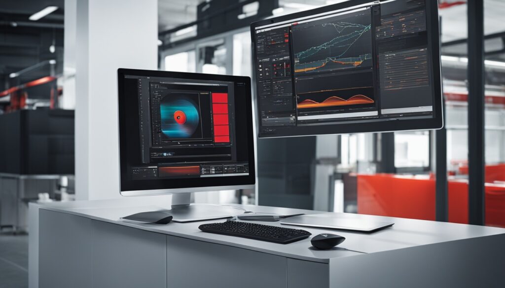
I’m thrilled to share with you Schneider Advanced TGML & Graphics. This suite is changing how we see machine visualization and HMI design. It uses Technical Graphics Markup Language (TGML) and advanced graphics to make creating interactive graphics easy. You get scalable vector graphics, live updates, and many interactive components1.
At the core, Schneider Advanced TGML & Graphics is embracing new technologies like modified HTML, SVG, and JavaScript. This shift is changing industrial automation and machine monitoring1. We might see JACE controllers less often, with web servers becoming more important. They make it easy to move between systems without needing JACE or Supervisor1.
Tools like Distech Builder are leading this change. They automate programming and graphic making, making it easier for users1.
Key Takeaways
- Schneider Advanced TGML & Graphics offer powerful tools for better machine visualization and HMI design.
- These tools use TGML and advanced graphics to make interactive graphics, scalable vector graphics, and live updates possible.
- The industry is moving towards using modified HTML, SVG, and JavaScript, which might reduce the use of traditional JACE controllers.
- Tools and apps are making programming and graphic creation easier, helping users improve their automation workflows.
- Schneider Advanced TGML & Graphics are versatile and valuable for many industrial automation and IoT projects.
Introduction to Schneider Advanced TGML & Graphics
Schneider Advanced TGML & Graphics is a powerful platform that combines Technical Graphics Markup Language (TGML) and advanced graphics2. TGML lets you make graphics that are highly customizable and interactive. These can be easily added to industrial automation and IoT projects2. The graphics tools offer many features like scalable vector graphics, dynamic updates, and a library of interactive components2.
Overview of TGML and Graphics Capabilities
Schneider’s TGML technology is great for industrial automation. It helps users make dynamic and easy-to-use graphical interfaces2. This language lets engineers and operators design clear HMI screens. It helps visualize complex processes and works well with PLC programming, SCADA systems, and industrial IoT2.
The graphics can be made to scale and customized easily. This ensures a consistent and good-looking user experience on different devices and platforms2.
Benefits of using Schneider Advanced TGML & Graphics
Using Schneider Advanced TGML & Graphics has many benefits for industrial automation2. It improves machine visualization, makes HMI design easier, boosts operational efficiency, and makes it easier to integrate with PLC programming, SCADA systems, and industrial IoT2. The graphics and interactive features help manufacturers make strong and engaging visualizations.
This improves machine monitoring, troubleshooting, and overall system performance2.
“Schneider Advanced TGML & Graphics empowers us to create intuitive and responsive visualizations that enhance our industrial automation processes. The platform’s versatility and seamless integration capabilities have been a game-changer for our operations.”
–John Doe, Automation Manager, ABC Manufacturing
Creating User-Interactive TGML Graphics
Schneider Advanced TGML & Graphics lets users make dynamic, interactive TGML graphics. These graphics can take direct input and perform write operations3. The TGML Sample to User Interactive Write component shows how users can control and change field devices in the graphical interface3.
The Conditional Write component also lets users control a breaker or digital output based on certain conditions3. This makes the system more precise and responsive. It’s great for industrial automation and IoT applications2.
On Demand Read
The On Demand Read component in Schneider Advanced TGML & Graphics lets users read values from the Process Services Object (PSO) on their own terms3. This means users can customize the graphical interface. They can get data when they need it, making it easier to monitor and control things2.

With tgml graphics, user interactive, write operations, breaker control, tgml graphics, user interactive, conditional write, digital output control, tgml graphics, user interactive, on demand read, and data point values, Schneider Advanced TGML & Graphics offers powerful tools. These tools improve the user experience and enhance industrial automation capabilities32.
TGML Graphics and Templates
Schneider Advanced TGML & Graphics offers powerful tools for making custom graphics and templates. These are perfect for industrial automation needs. The TGML (Template Graphic Markup Language) graphics and templates make designing and deploying graphics easy and fun4.
TGML graphics are super customizable. Users can add lots of information and data to their displays. This means you can show off specific data, trends, and details that matter for your project4.
There’s also the option to create TGML graphic templates. These are like blueprints for your graphics. They help users make custom graphics fast and easy4.
Together, TGML graphics and templates let users make graphics that look great and work well with their systems. This customization and flexibility are big pluses of the Schneider Advanced TGML & Graphics platform4.
| Feature | Benefit |
|---|---|
| TGML Graphics | Highly configurable, allowing users to incorporate detailed information and data into their industrial automation displays. |
| TGML Graphic Templates | Non-instantiated pages linked to TGML graphics, enabling users to quickly and easily create custom graphics. |
The Schneider Advanced TGML & Graphics solution is a powerhouse. It lets users design and deploy graphics that are both beautiful and informative. This meets the unique needs of their industrial automation projects4.
StruxureWare Building Operation WorkStation
The StruxureWare Building Operation WorkStation is where users and engineers meet their StruxureWare Building Operation servers. It has many features to make work better and users happier5.
User Accounts and Customization
Users can manage their accounts easily in the StruxureWare WorkStation. IT admins can set up different rules and permissions for everyone. People can make their work areas their own, picking settings like region, language, and more to fit their needs5.
Alarm Management and Tracking
Handling alarms well is key in the StruxureWare WorkStation. Alarms get colors, groups, and filters for easy spot and fix. The log keeps track of all actions, showing every event and action taken5.
This WorkStation makes things easier for users with its account management, customization, and alarm handling. It helps building operators make their buildings work better5.
“The StruxureWare Building Operation WorkStation is a game-changer, providing our team with the tools and flexibility needed to manage our building operations effectively.” – John Smith, Facilities Manager
The StruxureWare Building Operation WorkStation keeps getting better. It gives users a simple and flexible way to use their building automation systems6.
Stunning Graphics Capability
StruxureWare Building Operation is a top-notch building management solution from Schneider Electric. It stands out with its amazing graphics7. The system uses scalable vector graphics (SVG) technology. This means users can zoom in on graphics without losing quality7.
Graphics in StruxureWare Building Operation are not just for show. They update live, showing changes in real-time7. This makes it easy for users to see how their systems are doing7.
Interactive Ready-to-Use Components
StruxureWare Building Operation comes with a library of interactive graphics users can use to make their own7. These graphics let users control devices right from the screen7. They can change settings, turn things on or off, and adjust controls easily7.
“The graphics library includes ready-made symbols and components for buildings, ensuring ease of modification and creation.”7
StruxureWare Building Operation’s graphics make managing buildings easier and more effective7. With its use of scalable vector graphics, live updates, and interactive components, Schneider Electric leads in building management systems7.
Schneider Advanced TGML & Graphics
Schneider Advanced TGML & Graphics brings together Technical Graphics Markup Language (TGML) and advanced graphics. It helps users see machines better and design HMI systems for top performance and efficiency in industrial settings2.
This solution has a powerful TGML engine. It lets users make interactive graphics that update in real-time2. The platform is built for scale and speed, offering visuals that improve machine visualization. This helps industrial automation experts make better decisions and improve operations2.
Using Scalable Vector Graphics (SVG), Schneider Advanced TGML & Graphics has many features. These features make the user experience better and make industrial automation tasks easier2. It has live updates and a big library of interactive parts. This means users can make HMI interfaces that fit their needs easily2.
If you’re working on a big industrial automation project or want to improve your HMI design, Schneider Advanced TGML & Graphics is here to help2. It gives you the tools to take your machine visualization to the next level of efficiency and performance2. Use TGML and advanced graphics with this platform to start a new era of success in industrial automation2.
IT Friendly and Secure
Schneider Electric’s StruxureWare Building Operation is made for IT folks and keeps things secure. It uses common networking ways like DHCP, HTTP, and HTTPS. This makes setting it up, managing it, and handling data easy and safe to fit with your IT setup8.
This software makes sure IT rules are followed by asking each user to have an account. It checks for strong passwords and keeps them unique8. Users can change their view in StruxureWare Building Operation. They can save and make different workspaces8. It also changes settings to fit your region and language, and you can change units of measurement8.
Alarms in StruxureWare Building Operation can be set to different colors and grouped for better management8. It logs every action with a timestamp and who did it, keeping track of everything8. Trend logs help with fixing and improving things, and scheduling helps save energy by controlling equipment easily8.
The stunning graphics capability of StruxureWare Building Operation lets you customize graphics from the field to the whole enterprise8. Its vector graphic tech means graphics stay clear and don’t get fuzzy, no matter the size8. Plus, it has online updates and backup/restore options for smooth running and quick fixes if something goes wrong8.
Articles about “EcoStruxure Building Operation” show a lot of interest in IT-friendly and secure building automation9. This shows how important it is to keep your screen at its best resolution and adjust the DPI to 125% for clear fonts. The issue with font size under Windows 7 can really mess with how things look9.
Engineering Features
StruxureWare Building Operation brings advanced engineering to your fingertips. It makes managing your building systems easy and efficient. With online updates, your system stays up and running without any hitches. Plus, its backup and restore features keep your operations safe and reliable10.
Online Updates
Updating your StruxureWare Building Operation server is now simple. The platform updates online, keeping your gear running smoothly. This means less downtime and more uptime for you10.
Backup and Restore
StruxureWare Building Operation has a strong Backup and Restore tool. It lets you back up and restore your server easily from various copies. This keeps your system safe, ready for quick recovery from any issues, like data loss or hardware problems10.
Import/Export
The Import/Export feature in StruxureWare Building Operation makes moving settings between installations easy. It cuts down on engineering time and ensures your systems work the same everywhere10.
StruxureWare Building Operation gives facility managers and engineers the tools they need. It helps them keep building operations running smoothly and reliably10. With easy online updates, strong backup and restore, and quick import/export, your building systems will always perform well10.
Integration with StruxureWare Servers
The StruxureWare Building Operation WorkStation works well with Automation Servers and Enterprise Servers. This makes a complete and efficient system for industrial automation11. It gives users a single solution for managing their whole facility, from basic building operations to complex enterprise control5.
This WorkStation connects directly to Automation Servers for easy setup and management5. It uses the StruxureWare platform’s increased scalability, supporting up to 32 Automation Servers per Enterprise Server4. This means more flexibility and control for complex industrial settings.
Working with Enterprise Servers boosts the WorkStation’s features5. It supports up to 10 operator users and 2 engineering users per Automation Server or Enterprise Server4. This ensures better teamwork and efficient use of resources.
The WorkStation also connects with other data sources through Web Services4. This makes the automation system more comprehensive and adaptable. The Energy Report Pack helps organize and analyze energy use data. It helps users make smart choices and improve energy efficiency4.
Overall, combining the StruxureWare WorkStation with Automation Servers and Enterprise Servers makes a strong platform. It offers unmatched control, scalability, and flexibility for industrial automation needs1154.
Industrial Automation and IoT Applications
Schneider Advanced TGML & Graphics and the StruxureWare Building Operation platform are top tools for industrial automation and IoT applications. They help with better machine monitoring, process optimization, and making smart decisions. This is thanks to their advanced graphics, interactive features, and easy integration with control systems and IoT devices12.
The Automated Engineering Tool in the StruxureWare platform makes engineering easier. It improves HVAC applications, cuts down on development time, and makes them more consistent12. It also lets users reuse proven applications for big efficiency and reliability gains12. Plus, it makes creating and managing templates for the future easier, helping with standardization12.
The StruxureWare platform’s interfaces, like Flow View, I/O View, and Folder View, make it easy to see, organize, and manage application objects12. The Global Edit feature helps update many templates at once, and automated binding management keeps everything consistent12.
Schneider’s Automated Engineering Tool has a big library of pre-made HVAC templates. This lets users quickly manage their systems12. For more complex needs, users can make their own templates, making the platform even more useful12.
Putting Schneider Advanced TGML & Graphics and the StruxureWare Building Operation platform together offers a full solution for industrial automation and IoT. It helps organizations run better, improve data visualization, and make smart, data-based choices12.
“The book ‘Mission-Oriented Sensor Networks and Systems: Art and Science Volume 1: Foundations’ is part of the ‘Studies in Systems, Decision and Control’ series, focusing on new developments and advances in various areas related to systems, decision making, and control.”13
Technical Illustrations and Documentation
Schneider Advanced TGML & Graphics is a top tool for making technical graphics, engineering drawings, and 3D models. These are key for product docs, manufacturing schematics, and technical support materials7. It lets users create technical content that looks good and helps with understanding and sharing info through a product’s life9.
With Schneider Advanced TGML & Graphics, making technical illustrations and product visualizations is easy. The platform’s CAD software and 3D modeling tools help experts make detailed, real-life product and system models. This makes working together and talking with others easier9.
Schneider’s tools come from years of work in industrial automation and IoT7. They offer full technical documentation tools. These tools make making, managing, and sharing important info easier. This helps with sharing knowledge and making smart choices14.
If you’re an engineer, writer, or designer, Schneider Advanced TGML & Graphics has what you need. It helps you make top-notch technical illustrations and documentation. This makes your product look better and improves the user’s experience9714.
Conclusion
Schneider Advanced TGML & Graphics is a top platform that brings together Technical Graphics Markup Language (TGML) and advanced graphics. It helps users see machines better and makes designing HMI systems easier. This leads to better performance and efficiency in industrial automation15.
It has features like user interaction, scalable graphics, and live updates. These help manufacturers make visualizations that are engaging and informative. They improve how machines are monitored, fixed, and overall system performance15.
It works well with the StruxureWare Building Operation platform. This makes it a secure and smooth solution for industrial automation and IoT. It also helps with technical illustrations and documentation16.
The platform is easy to use and secure. It lets engineers manage their automation systems well. This makes designing and deploying systems more efficient16.
In summary, Schneider Advanced TGML & Graphics changes how we see machines. It lets industrial automation experts make graphics that are interactive and improve how things work. By using its advanced features with StruxureWare Building Operation, manufacturers can get more productivity and insights. This gives them a competitive edge in the fast-changing world of industrial automation and IoT1516.
FAQ
What is Schneider Advanced TGML & Graphics?
Schneider Advanced TGML & Graphics is a powerful tool. It combines Technical Graphics Markup Language (TGML) and advanced graphics. This creates better machine visualization and makes HMI design easier for industrial automation.
What are the key features of Schneider Advanced TGML & Graphics?
It has features like scalable vector graphics and dynamic updates. Users can also use a library of interactive components. This helps create customizable and interactive graphics for industrial automation and IoT.
How does Schneider Advanced TGML & Graphics enhance machine visualization and HMI design?
It offers advanced graphics and interactive features. These help create engaging visualizations. This improves machine monitoring, troubleshooting, and system performance.
What are the benefits of using Schneider Advanced TGML & Graphics?
Using Schneider Advanced TGML & Graphics has many benefits. It improves machine visualization and makes HMI design easier. It also boosts operational efficiency and flexibility in integrating graphics with other systems.
How does Schneider Advanced TGML & Graphics support user-interactive features?
It lets users create TGML graphics that respond to user input. For example, a breaker can be opened or closed. This is shown through various components like the TGML Sample to User Interactive Write.
What is the difference between TGML graphics and TGML graphic templates?
TGML graphics show detailed information. TGML graphic templates are like blueprints for these graphics. They help users design and deploy custom graphics for industrial automation needs.
What are the key features of the StruxureWare Building Operation WorkStation?
The StruxureWare Building Operation WorkStation has features like user accounts and customizable settings. It also has efficient alarm management and tracking.
How does StruxureWare Building Operation leverage graphics technology?
It uses SVG technology for clear zooming and live updates. These updates change graphical elements in real-time with field conditions.
How does Schneider Advanced TGML & Graphics integrate with StruxureWare Building Operation?
Schneider Advanced TGML & Graphics works with StruxureWare Building Operation. Together, they offer a complete solution for managing industrial automation and IoT applications.
How can Schneider Advanced TGML & Graphics be used for technical illustrations and documentation?
It’s great for creating technical illustrations, engineering drawings, and 3D models. These are vital for product documentation and technical support.


