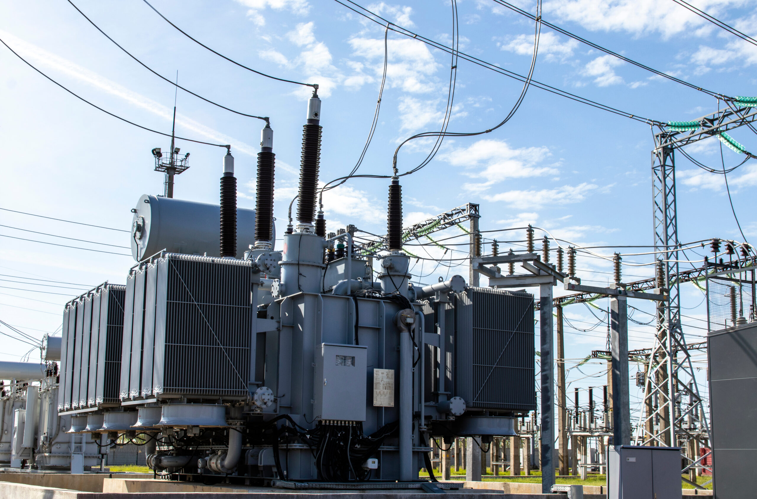
Two transformers can share the same voltage rating and the same MVA rating, yet act like different machines in service. If you treat them as identical, you can run into trouble with parallel operation, voltage control, losses, heating, and fault levels.
The difference sits in a handful of transformer parameters that shape how the unit behaves in the real system, not only on paper. Once you know what to read, the nameplate starts to tell a much richer story.
Why equal ratings don’t mean equal transformers
A 2 MVA transformer is not automatically interchangeable with another 2 MVA transformer. The big numbers tell you capacity and voltage level, but they do not tell you how the windings are connected, how the unit will cool itself, how it will respond to faults, or how much energy it will waste every day.
That matters in substations, industrial plants, and distribution networks. A transformer has to match the system around it. If it does not, the result can be poor voltage regulation, extra losses, overheating, nuisance alarms, or trouble when trying to run two units in parallel. If you need a quick refresher on how substation transformers work, it helps frame why these details show up on the nameplate in the first place.
This quick reference shows the five checks that separate two same-rated transformers:
| Parameter | What it tells you | Why it matters |
|---|---|---|
| Vector group | Winding connection, neutral, phase shift | Needed for correct system connection and parallel operation |
| Losses | Fixed core loss and load-dependent copper loss | Affects efficiency and lifetime operating cost |
| Tap changer | How the transformer adjusts voltage | Helps maintain acceptable output voltage |
| Cooling method | How heat leaves the transformer | Protects insulation life and loading capability |
| Impedance | Opposition to AC current | Changes fault current and voltage drop |
A broader transformer design parameters overview also shows how these choices fit into the larger design of a power system.
When two transformers match on voltage and MVA but differ in any of these five areas, they are not the same unit in practice. That is where selection starts.
Vector group tells you how the windings are connected
The vector group is one of the fastest ways to spot a meaningful difference between two transformers. Codes like DYn11 or YNd1 are not random. They tell you how the high-voltage winding is connected, how the low-voltage winding is connected, whether neutral is available, and what phase displacement exists between the two sides.
The capital letter refers to the HV winding. In that code, D means delta and Y means star. The lower-case letter refers to the LV winding, again using d and y for delta and star. The letter N or n shows whether neutral is brought out. That is a big deal on the distribution side, where loads are often unbalanced and a neutral is needed.
How to read DYn11
DYn11 is common on distribution transformers. In that code:
- D means the HV winding is delta-connected.
- y means the LV winding is star-connected.
- n means the LV neutral is available.
- 11 gives the phase displacement by the clock method.
The clock method uses 30 degrees per hour mark. So 11 means 11 x 30 = 330 degrees, which is the same as a 30-degree leading shift, depending on the reference you use.
This is not a small detail. If two transformers have different vector groups, they should not be paralleled as if nothing changed. A mismatch can cause circulating currents, extra heating, losses, and poor load sharing.
Matching voltage and MVA is not enough for parallel operation. The vector group also has to match.
That is why engineers often check the vector group first. It tells you, in one short code, whether the transformer even belongs in the same conversation as the other unit.
Transformer losses decide how expensive the unit is to run
Transformers are efficient, but none are loss-free. Those losses fall into two main groups, and the difference between them matters when you choose a unit for a real site.
The first group is core loss, also called iron loss. This loss comes from the transformer core and stays roughly constant as long as the transformer is energized at the rated voltage and frequency. It does not matter much whether the transformer is lightly loaded or fully loaded. Even with little or no load connected, core losses are still there. Hysteresis and eddy current losses sit in this category.
The second group is copper loss. This loss depends on load current, so it rises when current rises and drops when current drops. That is why copper loss is often called a variable loss.
A site’s load profile should guide the choice. Picture a factory that runs hard for only eight hours a day. For the rest of the time, the transformer stays energized but lightly loaded. In that case, high core loss becomes a steady drain because the transformer wastes power even during quiet hours.
Now compare that with a utility or industrial application where the transformer stays near 80% to 90% loading for long periods. There, copper loss becomes more painful because load current stays high for most of the day.
A cheaper transformer with higher losses can look attractive at purchase time and cost more over the years. That tradeoff is why losses belong near the top of any power transformer performance parameter checklist. Purchase price matters, but operating cost keeps showing up on the bill.
Tap changers keep the output voltage in range
Power-system voltage does not sit still. It moves with loading, reactive power, and changing system conditions. A transformer helps manage that movement through tap changers, which adjust the turns ratio and shift the output voltage without changing the whole grid upstream.
The idea is simple. Secondary voltage depends on primary voltage and the turns ratio between the windings. Since the system cannot casually change the incoming voltage from the source, the practical option is to change the number of effective turns on one side of the transformer. That is what taps do.
A transformer may have taps on the HV side or the LV side, depending on the design and application. The key question is how those taps are changed.
Off-load and on-load tap changers
An off-load tap changer needs a full shutdown. The transformer must be isolated, and the tap is changed manually. This method is simpler and cheaper, but it offers no real-time control. Step sizes can vary by project and manufacturer, often by a few percent at each position.
An on-load tap changer, often called an OLTC, can change taps while the transformer stays energized. That makes it a better fit where voltage needs active control. If system voltage drops, the OLTC can shift position and bring the output back toward the target range.
That convenience comes with a price. OLTC systems cost more and need solid maintenance. Poor upkeep of the tap-changing mechanism is a common source of transformer trouble. So when you compare two same-rated units, do not stop at “has tap changer” or “doesn’t have tap changer.” Check whether it is off-load or on-load, where the taps are located, and what adjustment range the transformer provides.
Cooling method protects transformer life
A transformer lives or dies by temperature. Once heat rises beyond the design limit, insulation ages faster, and transformer life starts shrinking. A common rule of thumb says a 10% rise in temperature can cut equipment life by 50%. Whether the exact number shifts by standard or application, the message is the same: heat is expensive.
That is why the cooling code on the nameplate matters. Common codes include ONAN, ONAF, OFAF, and OFWF.
ONAN means oil natural, air natural. The oil circulates naturally inside the transformer, and the surrounding air also moves naturally across the radiators. No fans, no oil pumps. This suits lower-capacity transformers or installations with easier thermal conditions.
ONAF means oil natural, air forced. The oil still moves by natural circulation, but fans push air across the cooling surfaces. Mid-range power transformers often use this method. Some transformers even carry dual ratings, such as 20 MVA under ONAN and 25 MVA under ONAF. In plain terms, the fan-assisted mode allows more loading.
OFAF means oil forced, air forced. Now pumps move the oil, and fans move the air. OFWF means oil forced, water forced, where water helps remove heat. These methods fit heavier loading and larger transformers.
Cooling also works in stages. At one temperature level, the first bank of fans may start. At a higher level, another stage may come on. If temperature keeps rising, the system may alarm or trip. That is why winding temperature indicators, oil temperature indicators, and maintenance checks matter. For a closer look at condition checks around insulation, impedance, and winding health, this guide to power transformer testing essentials adds helpful context.
Transformer impedance sets fault current and voltage drop
The last parameter often has the biggest effect on the fault level of the system: transformer impedance. You will usually see it on the nameplate as a percentage, such as 5%, 6%, 10%, or 12%.
In simple terms, impedance is the total opposition to AC current. It includes resistance and reactance together, so it tells you more than resistance alone. In a transformer, that percentage changes how much short-circuit current can flow during a fault.
If a short circuit occurs on the secondary side and the transformer has low impedance, say 2%, fault current can rise sharply because the transformer offers little opposition. If that same fault occurs on a transformer with much higher impedance, the short-circuit current will be lower.
That sounds like a reason to choose the highest impedance possible, but that creates a second problem. Higher impedance also causes higher voltage drop and poorer voltage regulation under load.
Low impedance raises fault current. High impedance lowers fault current but increases voltage drop.
So the right choice is a balance. You need to know how much voltage drop the system can tolerate and how much fault current the downstream equipment can handle. Circuit breakers, disconnectors, and other gear near the transformer must be rated for that short-circuit duty, and the breaker must interrupt that current safely.
This is where two same-rated transformers can part ways in a hurry. One might fit the available breaker duty and voltage-drop limits. The other might force changes to the rest of the installation.
Final thoughts
When two transformers sit side by side with the same voltage and MVA rating, the big numbers only tell part of the story. The real difference is often hidden in vector group, loss profile, tap-changing method, cooling code, and impedance.
Read those five items before calling two transformers “the same.” That habit leads to better decisions on selection, operation, maintenance, and parallel use.