AC runs nearly every part of the power system you touch, yet when you open a switchgear control box, DC is often the supply you find. That seems odd at first, because the main system around it may be 12 kV, 36 kV, or much higher.
The reason is not habit. Control and protection circuits must keep working when the main supply fails, and they need a steady source for relays, coils, and trip commands. Once you look at what those circuits must do during a fault, the split starts to make sense.
That split between AC in the power path and DC in the control path is where the whole story starts.
AC powers the load, but DC powers the commands
Every switchgear assembly has two electrical sides. One side is the rated normal voltage, which is the system voltage the switchgear is built to handle. In medium-voltage gear, that may be 12 kV, 24 kV, 36 kV, or 52 kV.
The other side is the auxiliary voltage. This is much lower, and it feeds the control and protection circuit. It does not carry the main load current. Instead, it powers the parts that tell the switchgear what to do.
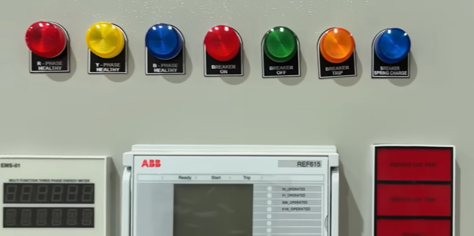
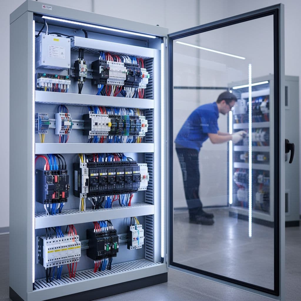
Inside a panel, that difference is often easy to spot. The power circuit handles the heavy current and the system voltage. The control circuit sits in the low-voltage compartment, where the relays, contactors, indication devices, and breaker control logic live. Many engineers also call these the main circuit and auxiliary circuit.
A car makes the same point in plain language. The engine may produce large mechanical power, but it does not use that full power to start itself. It uses a small starting action to wake the machine up. Switchgear follows a similar pattern. The main circuit carries the energy, while the control circuit sends the open and close commands that make the breaker act.
If you want broader context around the equipment discussed here, this guide to medium voltage switchgear gives a useful overview of where the control side fits into the whole assembly.
The main reason DC wins: it stays available when the grid does not
The strongest reason for DC is simple. DC can be stored in batteries.
Picture a 36 kV switchgear panel during a short circuit. Fault current rises fast, and the supply feeding part of the installation may collapse or disappear. If the control circuit also depends on AC from that same failing source, the relay may lose power before it can send a trip command. Then the breaker may stay closed while the fault keeps feeding the system.
That is the one moment when the control circuit cannot afford to go dark. The breaker must open, even during the fault that caused the problem.
If the AC source feeding the controls disappears during a fault, the breaker still has to trip. Battery-backed DC gives the protection chain a power source when it matters most.
This is why dedicated battery banks show up across the power system. You will find them in low-voltage panels, medium-voltage switchgear, and also in high-voltage and extra-high-voltage substations. The control circuit, the trip circuit, and much of the monitoring chain rely on that stored DC supply.
Gaurav J also explains the same point in a shorter written format in his post on why switchgear control circuits use DC instead of AC.
What control and protection circuits need from their supply
The choice between AC and DC is easier once you list the actual job of the auxiliary circuit. This part of the system is not there to deliver bulk power. It is there to react fast, stay stable, and keep protection dependable.
Fast, steady power for coils and relays
Circuit breakers often depend on simple but time-sensitive devices such as a trip coil and a close coil. When the control circuit issues a command, those coils have to act without hesitation. A weak or unstable supply can mean a breaker that fails to open or fails to close when commanded.
Relays also demand steady voltage. Protection relays monitor system conditions and decide when a breaker should trip. If the control voltage swings too much, relay behavior may suffer. In a protection chain, that is not a small issue. A missed trip or a false operation can both create trouble.
This is where DC helps. A battery-backed DC system provides a more stable auxiliary source, especially during disturbances. Even if the main AC system is under stress, the control side can stay ready.
Speed matters here, but stability matters just as much. Control circuits are full of small decisions that carry large consequences. A relay output, an interlock contact, or a breaker trip command may last only a moment, yet the supply behind that moment has to be dependable.
Compatibility, low interference, and safer working voltage
Component behavior also pushes designers toward DC. In many switchgear control boxes, contactors, relays, and similar devices are built to operate on DC auxiliary power. Some components can work with AC, but many control circuits are designed around DC as the standard choice.
Coils are a good example. A coil produces a magnetic field to move a plunger or operate a mechanism. DC gives it a steady magnetic effect. AC changes direction all the time, so the magnetic field alternates too. For certain control functions, that is not the desired behavior.
There is also the issue of electrical noise. AC creates alternating electromagnetic fields by nature. That can mean more interference around sensitive control and signaling circuits. DC reduces that concern.
Then there is safety. The low-voltage compartment is the part of the panel people interact with most often during testing, wiring, and maintenance. Auxiliary voltages such as 48 V DC, 110 V DC, or 220 V DC are far lower than the main system voltage. That lower level makes the control side safer to work around than the primary power path.
Why AC is a poor fit inside the auxiliary compartment
AC is excellent for generation, transmission, and distribution. It moves large amounts of power well, and the whole grid is built around it. Yet that does not mean AC is the best answer for every task inside a switchgear panel.
The auxiliary compartment has a different job. It has to keep logic alive, feed protection relays, operate coils, and hold up during a power loss. When you compare the actual needs of that compartment, DC matches them better.
This quick comparison shows why:
| Control-circuit need | Why it matters | DC supply | AC supply |
|---|---|---|---|
| Operation during power loss | The breaker must still trip during a fault | Can be stored in batteries | Not practical to store in the same way |
| Stable voltage | Relays and logic need predictable input | More stable for auxiliary use | More prone to variation during disturbances |
| Coil operation | Trip and close coils need firm magnetic action | Suits steady coil operation | Alternating field may be less suitable |
| Lower interference | Sensitive control circuits benefit from less noise | Lower electromagnetic interference | Alternating fields can add interference |
| Safer working level | Operators spend time in the low-voltage compartment | Common at lower DC values | Possible, but less common in this role |
The takeaway is simple. AC is the right tool for the main power path, but it is not the best tool for the control path. That is why AC control circuits in switchgear are possible, yet comparatively rare.
This design choice still holds even as equipment changes. Many future trends in switchgear technology focus on smarter monitoring and tighter integration, but dependable auxiliary power remains a basic requirement.
Common DC auxiliary voltages you will see
Once you accept that DC is the better fit, the next question is usually about voltage level. Control circuits do not all run at one universal value. Different projects, standards, and equipment families use different auxiliary voltages.
According to IEC 62271-1, Table 6 lists common DC auxiliary values such as 24 V, 48 V, 60 V, 110 V, 125 V, 220 V, and 250 V. Those are recommended values for AC switchgear and controlgear applications covered by that standard.
The important point is not the exact number alone. It is the relationship between the two sides of the panel. A switchgear lineup may handle tens of kilovolts on the main circuit, while the control side runs on a much smaller DC voltage chosen for relays, coils, interlocks, indications, and protective functions.
In practice, you may see 110 V DC or 220 V DC in many control schemes. Other installations may use 48 V DC or 125 V DC. Local practice and equipment standards can shift the choice, so the nameplate and schematic always matter more than assumptions.
The same logic carries into compact distribution gear as well. If you work around ring main units, this guide to ring main units gives helpful background on where those assemblies fit in medium-voltage networks.
For readers who want to move past the concept and into actual drawings, Gaurav J also points to his Circuit Breaker Control Schematic Masterclass, which focuses on reading breaker control schematics up to 800 kV.
Where you will see this in real installations
This is not a medium-voltage-only rule. The same pattern shows up across the electrical system.
Open a low-voltage switchboard and you may find DC on the control side. Move up to medium-voltage switchgear and the same idea appears again. Go farther into high-voltage and extra-high-voltage substations, and battery banks become even more obvious because the protection system has to stay alive through severe system events.
That wide use tells you something important. Engineers did not choose DC for control circuits because it is old or familiar. They chose it because the job demands a supply that can survive faults, keep relays stable, operate coils cleanly, and stay separate from the weakness of the failing AC source.
So while AC dominates the main power system, DC often protects it from the inside.
Final thoughts
The easiest way to remember this is to separate power delivery from power control. AC is excellent for moving energy through the grid. DC is better for the small but decisive tasks that tell switchgear when to trip, close, monitor, and protect.
When a fault hits, the control circuit cannot wait for the main supply to recover. That is why battery-backed DC remains the preferred choice in most switchgear control and protection circuits.
AC may carry the energy, but DC is what gives the protection system a dependable voice when the system is under stress.