Electromagnetic Compatibility (EMC) is one of the most important concepts in modern electronics and electrical engineering. As electronic devices become more powerful and compact, the risk of interference between systems increases significantly. Understanding EMC helps engineers design reliable equipment that operates correctly without disturbing other devices.
This article explains the fundamentals of Electromagnetic Interference (EMI), EMC principles, common interference sources, and practical design solutions.
What is Electromagnetic Interference (EMI)?
Electromagnetic Interference (EMI) occurs when unwanted electrical disturbances disrupt the normal operation of electronic equipment. These disturbances can originate from:
- Electrical devices
- Radio transmitters
- Switching power supplies
- Lightning
- Electrostatic discharge (ESD)
The disturbance generated by one device may cause another device to malfunction or behave unpredictably. For example, interference may cause:
- Distorted TV signals
- Communication failures
- Sensor errors in industrial machines
- Incorrect readings in medical equipment
According to the EMC principles described in the book, EMI can range from minor disturbances to catastrophic failures affecting critical systems.
What is Electromagnetic Compatibility (EMC)?
Electromagnetic Compatibility is the ability of electrical equipment to:
- Operate correctly in its electromagnetic environment
- Not generate excessive electromagnetic disturbance
In simple terms:
EMI = the problem
EMC = the solution
Engineers use EMC techniques to control interference and ensure different electronic systems can work together without conflict.
The Source–Coupling–Victim Model
A simple way to understand EMI problems is the three-element model:
1. Interference Source
The device that generates electromagnetic noise.
Examples include:
- Switching power supplies
- Digital circuits
- Motor drives
- RF transmitters
2. Coupling Path
The medium through which interference travels.
There are several coupling paths:
- Conducted coupling (through wires)
- Radiated coupling (through electromagnetic fields)
- Cable-to-cable coupling (crosstalk)
- Power line coupling
3. Victim Device
The equipment is affected by the interference.
This may include:
- Sensors
- Microcontrollers
- Communication systems
- Measurement instruments
If any one of these three elements is removed, the interference problem disappears.
Common EMI Coupling Mechanisms
Understanding interference paths is essential for EMC design. The most common mechanisms include:
1. Conducted Coupling
Conducted coupling occurs when interference travels through electrical conductors, such as:
- Power cables
- Ground wires
- Signal lines
A common example is Common Impedance Coupling, where multiple circuits share the same ground or return path. When high current flows in that shared conductor, it creates voltage fluctuations that can disturb sensitive circuits.
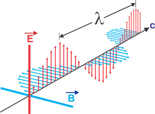
2. Radiated Coupling
Radiated coupling happens when electromagnetic waves travel through the air and are picked up by nearby cables or circuits.
Even simple wires can behave like antennas. When exposed to strong electromagnetic fields, they can capture energy and convert it into unwanted voltage signals.
Examples include:
- Radio transmitters affecting nearby electronics
- Radar signals are interfering with vehicles
- Lightning-induced voltage in cables
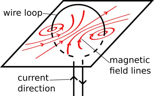
3. Cable Crosstalk
When two cables run close together, signals from one cable can couple into the other cable through:
- Capacitive coupling
- Magnetic coupling
This effect is common in communication systems and high-speed digital circuits.
EMC Testing Categories
To ensure devices meet EMC requirements, engineers perform several tests. These tests are generally divided into four major categories.
Conducted Emissions (CE)
Measures noise traveling through power cables.
Radiated Emissions (RE)
Measures electromagnetic radiation emitted by equipment.
Conducted Susceptibility (CS)
Tests how the equipment reacts to disturbances injected through cables.
Radiated Susceptibility (RS)
Tests how equipment responds to external electromagnetic fields.
These tests ensure devices both limit interference and remain immune to disturbances.
Why Decibels Are Used in EMC
EMC engineers commonly use decibels (dB) instead of standard units.
This is because electromagnetic signals can vary across extremely wide ranges. For example:
- A sensitive receiver may detect microvolt signals
- Power disturbances may reach thousands of volts
Using a logarithmic scale simplifies calculations and measurement comparisons.
Practical EMC Design Tips
Engineers can reduce EMI problems by applying several simple design practices:
Proper Grounding
Use star grounding or ground planes to prevent shared impedance problems.
Shielding
Metal enclosures and shielded cables help block electromagnetic radiation.
Filtering
EMI filters reduce high-frequency noise on power and signal lines.
Cable Management
Keep sensitive signal cables away from high-power circuits.
Short Return Paths
Reducing loop area minimizes interference pickup.
Why EMC Is Important Today
Modern electronics operate at higher frequencies and faster switching speeds than ever before. As a result:
- Devices generate more electromagnetic noise
- Systems become more sensitive to interference
- Wireless communication is more crowded
Without proper EMC design, electronic systems may experience:
- Random system failures
- Communication loss
- Data corruption
- Safety risks
Therefore, EMC is now a critical discipline in industries such as:
- Telecommunications
- Automotive electronics
- Aerospace systems
- Industrial automation
- Consumer electronics
Conclusion
Electromagnetic Compatibility ensures that electronic devices can operate reliably without interfering with each other. By understanding EMI sources, coupling paths, and mitigation techniques, engineers can design systems that meet modern reliability and safety standards.
As electronic technology continues to evolve, EMC knowledge will remain essential for developing robust and interference-free equipment.