When you connect software to a PLC, you’re usually trying to answer a simple question: how do I read and write real machine data without building a fragile one-off integration? That’s where OPC UA earns its place. It gives you a standard way to expose PLC tags (and more than tags) so many different tools can consume them safely.
This lesson covers the basics: why teams move past Modbus for certain use cases, what OPC UA is, how OPC evolved into OPC UA, and how the server and client pieces work together in a plant setup.
Why teams often move from Modbus to OPC UA
If you’ve worked with Node-RED and PLC connectivity, you’ve likely seen Modbus used as the quick path to read and write registers. It’s common because it’s simple, widely supported, and easy to test.
In earlier PLC connectivity setups, typical topics include:
- Modbus with Delta PLC
- Modbus with Siemens PLC
- S7 connection in Siemens PLC
Those approaches work, but Modbus has a big limitation that shows up fast in real plants: security. Modbus doesn’t include built-in user authorization. In many cases, if someone knows the IP address and port, they can connect and attempt to read or write.
This becomes a somewhat unsafe operation in the industry.
That risk is not theoretical. When write access is available, a bad actor (or even a well-meaning person using the wrong tool) can flip bits or change registers. That can impact outputs, actuator states, or interlocks, depending on how the PLC program maps Modbus data.
OPC UA is often chosen because it adds security layers. Instead of “anyone who can reach the port can talk,” OPC UA supports authentication concepts and secure sessions. In addition, OPC UA tends to fit better when you need many software systems to connect to the same PLC data in a consistent way.
If you want the full course track that pairs OPC UA with Node-RED, the video references Learn OPC UA with Node-RED.
What OPC UA is, and what it’s designed to solve
Definition and purpose
OPC UA stands for Open Platform Communications Unified Architecture. It’s an open communication standard for machine-to-machine communication, and the OPC Foundation developed it.
In a PLC-focused context, the main goal is practical: expose PLC data in a standard format so external systems can read it, and sometimes write it, using a consistent model. That can mean an HMI, SCADA, simulation software, a gateway, Node-RED, or a custom app.
Unlike ad-hoc drivers for each PLC brand, OPC UA is meant to be a shared “language” between industrial devices and software.
For a reference straight from the source, the OPC Foundation maintains an official overview page on OPC UA, see the OPC UA overview from the OPC Foundation.
Key features that show up in real projects
OPC UA gets described in many ways, but these four characteristics are the ones you usually feel during implementation:
- Integrated information model
OPC UA isn’t only “tag reads.” It uses a standardized structure based on nodes. Each data item has a NodeId and follows a defined syntax. Clients browse and address these nodes, which helps keep data organized and discoverable. This matters even more when you build your own server, because you decide how your address space is structured. - Open source availability
There are open source OPC UA servers and clients. In practice, that means you can often test without paying for tooling up front. It also means you can prototype quickly before choosing a vendor stack. - Secure model
Compared to Modbus-style access, OPC UA supports security concepts such as user authorization and checks before a server accepts a request. The result is not “perfect security by default,” but a platform designed with security in mind. - Cross-platform support
Many modern tools support OPC UA. One example from the lesson is Visual Components, a 3D CAD and simulation tool. With an OPC UA link, simulation software can reflect real PLC values, which is useful for testing logic and behavior against a model.
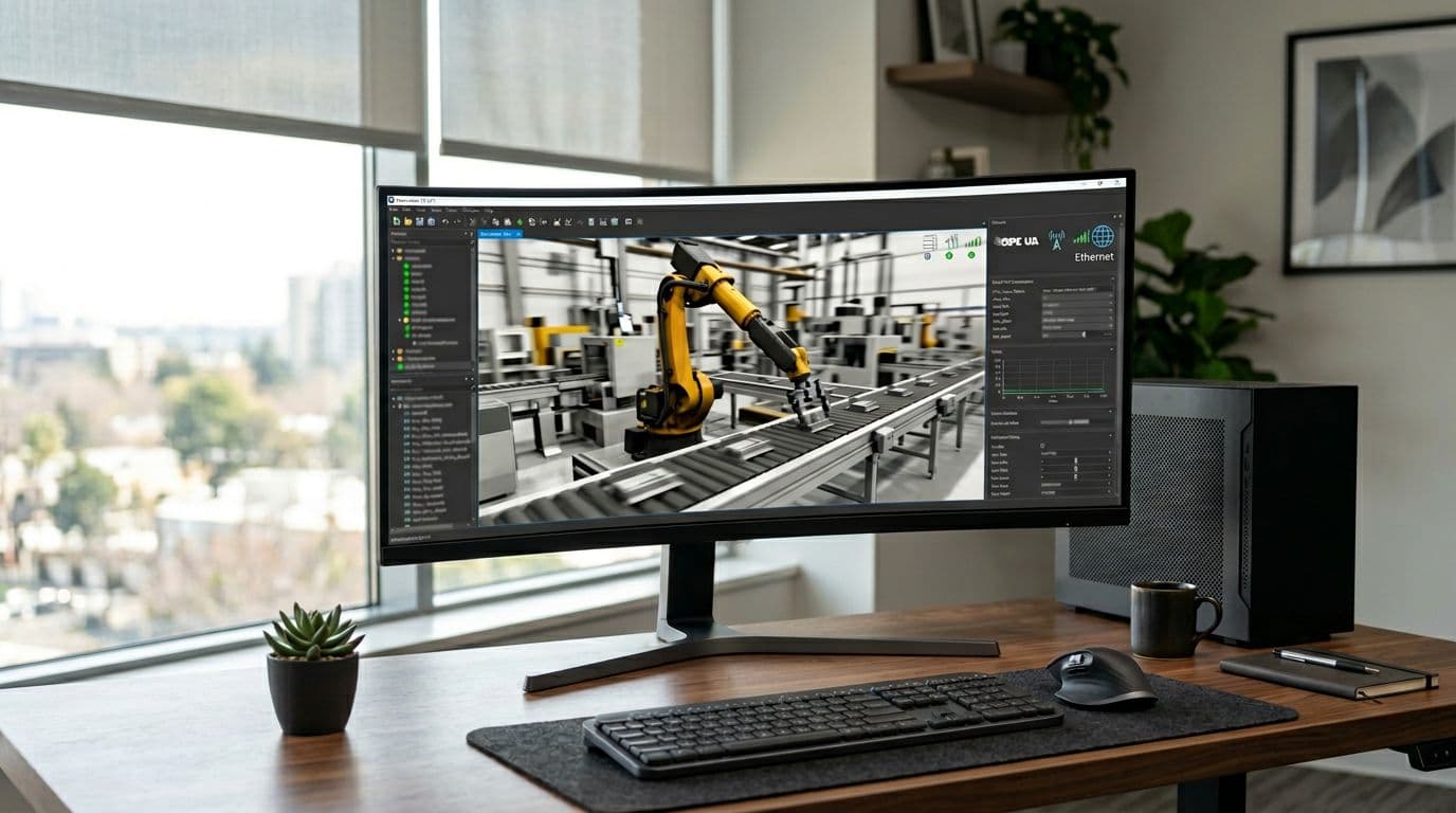 An example of simulation software connected to PLC data through OPC UA.
In other words, OPC UA helps bridge physical systems (sensors, actuators, PLCs) to software systems (simulation, analytics, dashboards) without rewriting the integration each time.
How OPC evolved into OPC UA (and what “Unified Architecture” means)
Before OPC UA, OPC “Classic” was split into different specifications depending on the type of data you needed. The lesson highlights three common ones.
Here’s a simple timeline-style view:
- OPC DA (Data Access): Focused on exchanging data values, including value, time, and quality.
- OPC A&E (Alarms and Events): Focused on alarm and event notifications.
- OPC HDA (Historical Data Access): Focused on historical data, including timestamps for when changes happened.
OPC UA pulls these concepts together into one approach. That’s why “UA” matters: Unified Architecture. Instead of picking a separate interface for real-time values versus alarms versus history, OPC UA is intended to cover them in one framework.
If you want a deeper comparison that stays focused on practical differences between old and new OPC styles, this internal reference is useful: OPC DA vs OPC UA key differences.
The key idea is consistency: one architecture that can represent data, alarms and events, and time context, while supporting secure communication.
The lesson also mentions a short explainer video link that will be shared alongside the course material. The point is clear: don’t get stuck in theory too long; move quickly into hands-on server and client work.
OPC UA in a plant setup: server, client, and data flow
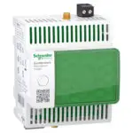
The OPC UA server acts as the data host
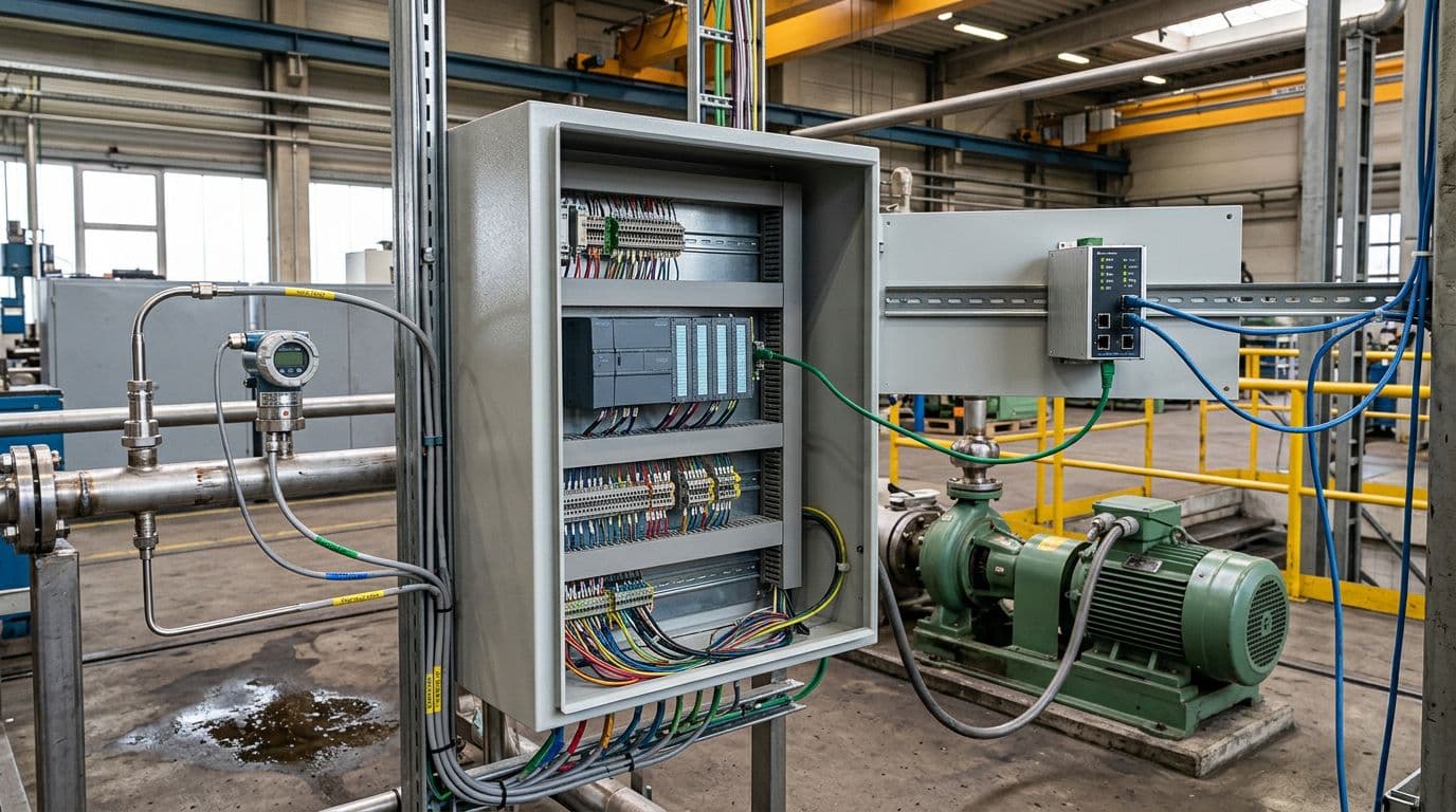 A PLC cabinet representing a common place where OPC UA server data originates.
In OPC UA, you usually talk about two roles: server and client. If you’ve used Modbus, the pattern will feel familiar: the server hosts data, the client consumes it.
An OPC UA server can run on many device types:
- A PLC (if it includes an OPC UA server feature)
- An IoT device
- An edge server
- A Raspberry Pi
- A computer
A key clarification from the lesson is that the “server” isn’t a special piece of hardware. It’s software, meaning it’s a program (code) running inside a device. When you “create an OPC UA server,” you’re creating and configuring that software component and its address space.
On the plant floor, a server device often becomes a hub because it already gathers data from many sources. For example, it may collect:
- Sensor values (temperature, level, pressure)
- Actuator state (on/off) and actuator operating data (like speed for a conveyor)
- Data from another PLC via Modbus
- IO-Link device data
- RFID reads
- Profinet-connected devices such as a VFD, AC drive, or servo drive
Once the server has that mix of signals, it exposes a structured model so clients can browse and access what they need.
The OPC UA client reads and writes, often from multiple tools
An OPC UA client is the consumer side. It can read values from the server and, if permissions allow, write values back. That’s the same basic idea as a Modbus client.
The client can be hardware or software. The lesson calls out examples like:
- Node-RED (commonly used as an OPC UA client in practical integrations)
- Raspberry Pi (running client software)
- Automation Studio (used for automation and simulation workflows)
- Visual Components (3D simulation connected to PLC data)
- UAExpert (a common OPC UA client tool used frequently in training and testing)
Another important point is role flexibility. One device can be both a server and a client. For example, an edge computer might run an OPC UA server for local apps, while also acting as a client to read data from PLC servers upstream.
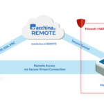
How OPC UA moves data through a secure channel
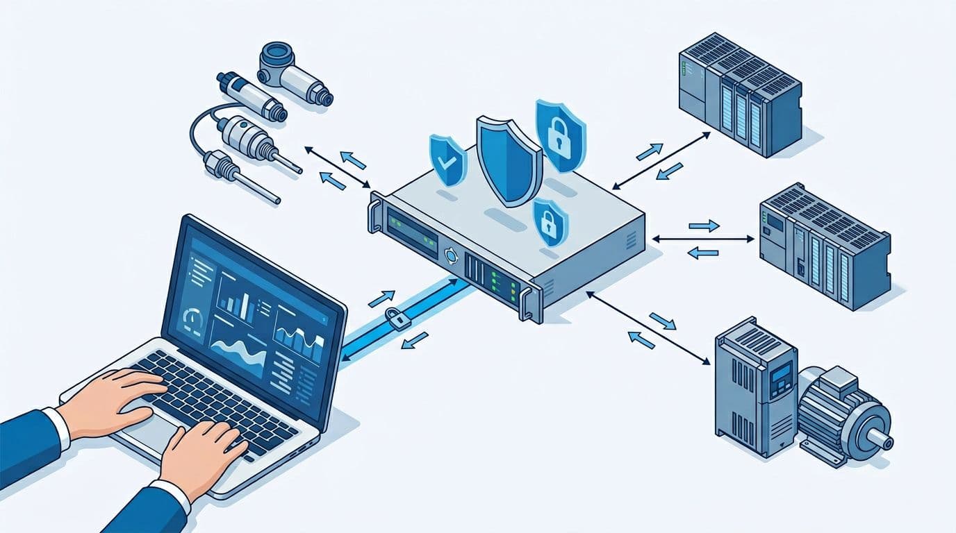 An OPC UA server-client connection showing secure data flow and read/write paths.
OPC UA communication follows a request and response pattern, but with security checks before the server shares data. The simplified flow described in the lesson looks like this:
- The client sends a request to the server.
- The server checks whether the certification or user authorization is valid.
- If the request passes, the server approves and sends the response.
That security step is the practical difference you feel when moving from “open register access” approaches to OPC UA sessions.
OPC UA also supports a common plant pattern where one client connects to more than one server. That matters because clients can act as a data bridge:
- The client reads from Server 1 and writes to Server 2.
- The client reads from several servers and sends selected values back to one server.
- The client shares values between different parts of a plant that do not directly talk.
In the lesson’s terms, servers don’t “talk to each other” by themselves in this pattern. The client becomes the messenger that reads, transforms if needed, and writes.
OPC UA because it’s a standardized uniform architecture.
If you’re thinking about where this fits in a wider IIoT design, it often sits between the controls layer and higher-level platforms. A useful next read for that broader selection process is IIoT platforms with OPC UA support, since platform choice affects how you handle identity, data routing, and long-term ownership.
Simulation first, then PLC data: what comes next
This first lesson sets up the mental model. The next practical step is usually to run an OPC UA server on a computer using free simulation software, then connect to it using an OPC UA client. That makes it easier to learn browsing, NodeIds, and read/write behavior before you connect to a real controller.
The upcoming progression described in the lesson is:
- Use a simulated OPC UA server on your computer (free to download).
- Connect using a client tool (UAExpert is mentioned as a common tool used in the course).
- Move from simulated tags to real PLC values.
- Later, build your own OPC UA server to understand the information model in detail.
For the course ecosystem and updates mentioned in the video description, these are the official channels: Code and Compile on Instagram, the Code and Compile online school, the Code and Compile wiki, and Code and Compile on LinkedIn.
OPC UA is a practical answer to a common plant problem: many systems need the same PLC data, but you still want structure and security. It builds on the older OPC concepts (data, alarms and events, history), but packages them into one unified approach with a standardized information model. Next, the fastest way to build confidence is to run a simulated server and connect with a client tool, then carry that workflow to a real PLC setup.