You can read ladder logic all day and still miss the part that matters most, how the PLC behaves when inputs change over time. That’s where TIA Portal simulation helps. With PLCSIM, you can run your project without a physical CPU, then watch bits, networks, and latch behavior in real time.
This post walks through a simple conveyor example, then shows how to start PLCSIM, download your program into the simulated PLC, monitor logic states, and drive inputs from a simulation table. It also covers a more advanced option, sequences, which can automate input changes like a timed demo.
Quick recap: the small conveyor system and OB1 logic
The project is intentionally simple, but it uses patterns you’ll see in real machines: sensor inputs, a motor output, a stopper actuator, and a small amount of memory behavior (set and reset).
The physical story looks like this:
- A workpiece is placed at the start of the conveyor.
- B1 detects the piece.
- The operator presses S1 (start pushbutton).
- The conveyor motor K1 turns on and stays on.
- When the piece reaches B2, the stopper actuator opens (output Q101).
- When the piece reaches the end sensor B3, the conveyor turns off, and the cycle ends.
The program is in OB1 and uses two main ideas:
- Set/reset (SR) behavior for the conveyor motor: when B1 and S1 are true, the program sets K1. Once set, K1 stays on even after S1 is released and even after B1 drops out (because the piece moved away).
- Direct assignment for the stopper: when B2 is true, output Q101 turns on directly. When B2 goes false, Q101 turns off, so the stopper closes again.
One detail matters for simulation and debugging: B3 is treated as a normally closed (NC) contact in the logic. The behavior described is that B3 is high when there is no workpiece, and it goes low when a workpiece is present. That is the opposite of many sensor conventions, so you often need to invert it in software or be very clear about how the tag is defined. In this example, the NC contact makes the reset path behave as intended once the input matches that “high when clear, low when blocked” sensor behavior.
If you want background reading on Siemens platforms used with TIA Portal, this overview of the Siemens SIMATIC S7-1500 PLC helps frame where PLCSIM fits in typical workflows.
Why simulate in TIA Portal instead of guessing
Simulation beats guessing because it shows you timing, latching, and contact behavior as it really executes. You can explain a rung, but the moment you toggle an input and see a coil stay set, it clicks.
It also helps you separate two common questions:
- Is the logic wrong?
- Or is the I/O assumption wrong (NO versus NC, inverted sensors, wrong tag address)?
PLCSIM is a simulation, not a full hardware emulation. It focuses on program execution and I/O interaction inside the engineering environment. You can choose what scope you want to simulate, from just program variables to the full device level.
Once you’re online and monitoring, TIA Portal uses clear visual cues:
- Blue dashed path indicates logic 0 (false); the rung is not energized at that segment.
- A green solid path indicates logic 1 (true); the rung has continuity at that segment.
That view is useful when you have a rung that “should work” but doesn’t. You can see exactly where continuity stops, often at a contact that never becomes true.
A practical note: starting a simulation typically disables other interfaces for that PLC instance, so you can’t connect to a real CPU and the simulated CPU at the same time. That prevents accidents and confusion when downloading.
Setting up PLCSIM and starting a full device simulation
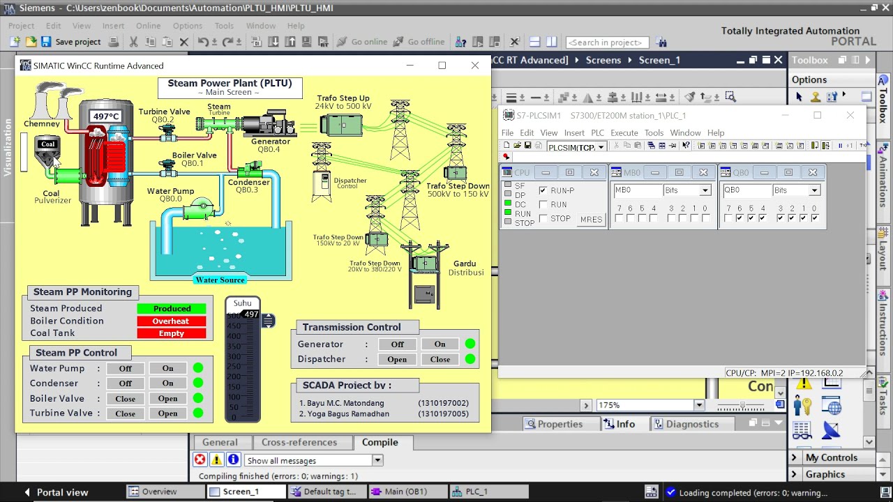
To simulate the whole PLC project, select the CPU (the “brain” at the top of the device tree). Then start simulation using the Start Simulation option (toolbar or context menu). This launches SIMATIC PLCSIM for S7-1500 and S7-1200.
PLCSIM is not always installed as part of the base TIA Portal install. You download it separately from Siemens. The download referenced in the video description is the Siemens support page that includes trial packages. You scroll down until you find the STEP 7 PLCSIM entry: SIMATIC STEP 7 and WinCC trial download page (includes PLCSIM).
After installation, start the simulation again from TIA Portal. If a prompt appears saying simulation is currently off, enable it for the PLC. In general training setups, this is fine, but it’s still a setting worth noticing since it changes how the environment behaves.
Once PLCSIM opens, TIA Portal compiles the project and brings up the download window. If compilation succeeds (no errors), download the program into the simulated PLC. After download:
- Finish the download dialog (modules can stay at “No action” for this basic case).
- Switch the simulated PLC to RUN. This is the same concept as turning a key switch or using the display controls on a real CPU.
Now, go online in TIA Portal. When everything is consistent, the device status indicators show green, meaning the project in the engineering station matches what’s in the PLC (in this case, the simulated PLC).
Finally, start monitoring by selecting the glasses icon. At this point, you can watch each rung energize. You typically see the left rail energized (logic 1) and then the path stops at the first input that is still false, such as B1, before a part is present.
If you’re working in newer environments, it also helps to know what changed across versions. This walkthrough of TIA Portal V20 Update 4 features gives context on stability and workflow improvements that affect compile, download, and diagnostics.
Running the basic conveyor test with expanded view and simulation tables
PLCSIM opens in a compact view first, but the expanded view is where simulation becomes easy to drive. Switch to the expanded mode (full view). In that view, you can create a simulation “project” and load the device configuration. You’ll see the PLC and its I/O, and you can toggle bits directly.
For controlled testing, use simulation tables (often called sim tables). Open a sim table and load the project tags. This pulls in the symbols you already use in the program, such as B1, S1, B2, B3, K1, and Q101. A small warning from the workflow shown: loading project tags repeatedly reloads entries rather than syncing them, so it’s best to load once and keep the table clean.
With the tags visible, you can walk through the process in a way that matches the machine:
- Set B3 to represent “no part at the end sensor.” In the described behavior, B3 is high when clear, so you force it to be true to start from an idle state.
- Place a part at the start by setting B1 true (a normal open detection in this example, the contact closes when the part is present).
- Press S1 true briefly. As soon as the logic sees B1 and S1, K1 is set.
- Release S1. The conveyor stays on because the set output remains latched.
- Move the part away from the start sensor by setting B1 false.
- Trigger the mid sensor by setting B2 true. This directly turns on Q101 (the stopper opens).
- Clear B2 again. The direct assignment drops Q101, and the stopper closes.
- Trigger the end condition at B3 by changing it to represent “part present.” In the described sensor convention, that means B3 goes low. When the NC contact closes in logic, it drives the reset that turns off K1.
This is the key check: does the conveyor motor stay on after S1 is released, then turn off only when the B3 reset condition is met? If it behaves that way in PLCSIM, the OB1 logic and tag wiring are consistent with the intended sequence.
Automating the same test with PLCSIM sequences (timed input changes)
Manual toggling is fine for a first pass, but PLCSIM sequences help when you want repeatable timing. A sequence is a list of input changes that play back automatically, often tied to a trigger.
In the workflow shown, the sequence is triggered when K1 becomes true. That’s important because K1 is controlled by the PLC program, not by the sim table. Once K1 turns on, the sequence starts stepping through the sensor changes as if the part is moving down the conveyor.
The sequence is set to use seconds, with one action every 5 seconds. The steps mirror the manual demo:
- After K1 turns true, set B1 false (the part moved away from the start sensor).
- Set B2 true (the part reaches the stopper sensor, so the stopper opens via Q101).
- Set B2 false (the part has passed the sensor, so the stopper closes).
- Change B3 to indicate that the part reached the end, which in this example means B3 goes low and the reset condition becomes true, so K1 turns off.
- Optionally return B3 to the “clear” state after the part is removed, so the system is ready for the next cycle.
Once the sequence is configured, start it. It waits for the trigger (K1 true). Then you only do the operator actions:
- Set B1 true to place a part.
- Press Pulse S1 to start the conveyor.
From there, the sequence drives B1, B2, and B3 automatically on a fixed schedule. When you watch the ladder online, you can see the same chain of events as the manual test, but with consistent timing. That makes it easier to confirm that the direct assignment to Q101 responds instantly to B2, and that the SR latch for K1 only resets when the B3 logic path becomes true.
If you’re building skills beyond a single demo, consistent practice matters more than one perfect project. This longer guide on TIA Portal PLC simulation software and learning paths is useful for structuring hands-on work around simulation, debugging, and commissioning habits.
Practical notes: NO vs NC, inverted sensors, and connection limits
A few details from this setup show up in real commissioning work.
First, NO versus NC matters twice, once in wiring and once in logic. A sensor can be physically wired as NC for safety reasons, but you still need to decide whether the PLC tag represents the raw electrical state or the “part present” meaning. In this example, B3 is treated in a way that can confuse new users: “no part” reads high, and “part present” reads low. That makes the NC contact in the rung behave as intended for the reset, but it also means you need to be careful when forcing values in PLCSIM.
Second, simulation can hide wiring mistakes, but it can also reveal logic mistakes faster. If the rung path stops early in monitoring, the issue is often a single input that never changes state the way you think it should.
Third, when simulation is active, TIA Portal typically prevents using that same PLC interface for a real CPU connection at the same time. That’s by design. Treat the simulated PLC as its own target.
Finally, PLCSIM for S7-1500 and S7-1200 is not the same toolset as the older families (S7-300, S7-400, S7-200). The workflow and interface can look different there, so make sure you’re using the correct simulator for your PLC family.
Conclusion
Simulation turns a ladder diagram into behavior you can see, measure, and repeat. With TIA Portal and PLCSIM, you can download OB1 into a simulated S7-1500, force inputs like B1 and S1, then confirm that K1 latches and resets exactly where you expect. Once the manual test works, sequences add timing and repeatability, which is a big step toward realistic debugging. If your conveyor doesn’t behave correctly, the monitoring colors usually show where the logic stops.