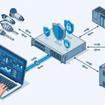
Walk into almost any European control panel and you’ll notice a pattern: when a Variable Frequency Drive (VFD) is involved, overcurrent protection is rarely a breaker-only affair. You’ll see fast-acting fuses, coordinated protective devices, and very specific wiring notes in the manual. That’s not an accident or a quirk—it’s the convergence of physics, semiconductor survivability, and the IEC approach to safety coordination.
👉 Why European VFD manufacturers are reluctant to accept breakers only as the sole protection of drives
This article explains why many European VFD manufacturers are reluctant to accept circuit breakers as the sole means of protection for drives. We’ll unpack the electrical and mechanical realities inside a VFD, the limits of generic breakers during short circuits, the logic of IEC coordination (“Type 1/Type 2”), the role of semiconductor fuses, warranty and compliance considerations, and practical panel-building implications. By the end, you’ll understand not just the what, but the why—and you’ll have a practical framework for specifying protection that aligns with European expectations.
Quick refresher: what a VFD really needs protection from
A VFD isn’t a passive load; it’s a high-energy, high-speed power conversion system. Its most vulnerable elements are semiconductor devices—the rectifier diodes, the DC-link capacitors, and especially the IGBTs or MOSFETs in the inverter stage. These components can switch tens of amps in microseconds, but their tolerance to fault energy is surprisingly limited. They fail not like copper busbars (which can ride out significant thermal surge) but like delicate fuses—except with catastrophic consequences if they go beyond their limits.
Three categories of stress matter most:
- High fault current on the AC side (line side short)
If the supply sees a short, the protective device must limit and clear the fault extremely quickly to prevent let-through energy from vaporizing the drive’s input stage or damaging its DC bus. - DC-bus and inverter faults (internal or motor side)
Semiconductor junctions have very low thermal mass. They can endure short, controlled surges (e.g., inrush into capacitors), but not uncontrolled fault energy. An upstream device must act fast enough that semiconductor I²t ratings aren’t exceeded. - Transient and cumulative thermal stress
Repetitive stresses (like nuisance short spikes or repeated minor faults) can weaken semiconductors and capacitors. Protection needs to prevent both catastrophic failure and long-term degradation.
Because of these realities, protective devices for drives aren’t just about meeting cable ampacity rules. They must coordinate with the semiconductor survival envelope. That’s the crux of the European stance.
Breakers are great—but not great for everything
Let’s be clear: circuit breakers are essential. They provide resettable protection, enable isolation, and are integral to selectivity. But a generic breaker has design priorities different from what a VFD’s semiconductors need during faults:
- Trip curve vs. semiconductor i²t
Thermal-magnetic breakers and even many electronic trip breakers respond according to standardized curves. These curves are excellent for protecting cables and general-purpose loads. However, semiconductors often need protection within a much smaller i²t window than what a breaker’s instantaneous or short-time bands can deliver—especially under high prospective fault currents. - Let-through energy and clearing time
In the first half-cycle of a bolted short, let-through energy can already exceed what a drive can tolerate. Many breakers, unless specifically designed and rated for current-limiting performance at the exact available fault level, may not limit i²t enough to save the inverter. - Coordination specificity
VFD manufacturers test and publish combinations that ensure their drives survive faults (“Type 2 coordination” in IEC terms). A random breaker may not be part of that validated pairing, so the manufacturer cannot guarantee survival under all credible faults. - High DC link inrush and nuisance tripping
Drives have significant inrush currents when charging DC capacitors. Breakers selected only by steady-state current may nuisance-trip or force you to escalate breaker frame sizes, which then reduces protective tightness during actual faults—an awkward trade. - Arc-flash and mechanical dynamics
For high available fault currents, the speed and limitation offered by semiconductor fuses (or very specific current-limiting breakers) can reduce arc-flash energy significantly. A general breaker’s mechanics may not be fast enough to cut incident energy to the desired level.
None of this means breakers are “bad.” It means breakers alone—without coordination, without fast fuses, without device-level testing—may not be sufficient to protect a VFD’s vulnerable parts or to meet the manufacturer’s stated requirements and warranties.
The European (IEC) philosophy: coordination and device-specific protection
European VFD manuals and data sheets often reference IEC concepts that emphasize coordination—verifying that the protective device and the protected equipment behave predictably under fault.
Two ideas loom large:
- Type 1 vs Type 2 coordination
- Type 1: After a short-circuit, the protective device prevents hazards, but the equipment may be damaged and may not be reusable without repair.
- Type 2: After a short-circuit, the equipment does not sustain damage (or at most minor contact welding), and can be returned to service without replacing parts.
- SCCR (Short-Circuit Current Rating) as installed
In the IEC world (and similarly in UL frameworks), declared SCCR depends on the combination of the drive and the protective device. Manufacturers validate specific pairs (e.g., “Use aR/gR fuses of type XYZ, rated xx A, to achieve 50 kA SCCR”). If you choose a breaker outside the validated list, you may void that SCCR and the warranty claim that rests on it.
This approach reflects a fundamental premise: the drive’s survival envelope is not generic, and the protective device must be matched to the drive to guarantee outcomes under fault.
Why semiconductor fuses are the star of the show
You’ll frequently see European documentation calling for aR/gR (ultra-fast) semiconductor fuses upstream of a VFD. Reasons include:
- Extremely low i²t let-through
Semiconductor fuses are engineered to interrupt within microseconds to milliseconds, limiting the energy that reaches the drive’s input rectifier and DC bus. - Predictable behavior at high prospective fault currents
They maintain performance up to very high kA ratings, giving a reliable SCCR when combined with the drive. - Selectivity and backup protection
When coordinated properly with upstream devices, they clear local drive faults without taking out the entire panel, preserving uptime elsewhere. - Nuisance-trip avoidance for inrush
Properly sized semiconductor fuses can ride through DC link inrush better than an oversensitive breaker instantaneous setting, reducing nuisance trips without weakening fault protection.
Because of these qualities, European VFD makers often specify “breaker + semiconductor fuse” or “fuse-switch disconnector” arrangements—combining convenient isolation and switching with true semiconductor-grade short-circuit protection.
“But I have a current-limiting breaker!”—still not a blanket green light
Modern current-limiting breakers can be exceptionally fast and may, in some cases, be approved by a drive manufacturer as a sole protective device. However:
- Approval is device-specific
The breaker model, trip unit settings, frame size, and even cable lengths must match the tested configuration. If the drive’s manual lists “Breaker ABC at setting X with cable Y,” that’s what you must implement. - Performance varies with installation
Available fault current, conductor impedance, and system topology can shift the breaker’s real-world let-through energy. If your installation differs materially from the tested scenario, you can lose the margin that was protecting the semiconductors. - Coordination with downstream protective devices
If the VFD feeds multiple loads (multi-motor drives, bypass arrangements), selectivity becomes more complex. A fuse-based approach often simplifies achieving selective coordination.
Bottom line: a sophisticated breaker may be allowed, but only when the VFD manufacturer says so, for that specific configuration. In the absence of such a listing, expect a recommendation (or requirement) for semiconductor fuses.
Warranty, liability, and the manufacturer’s risk calculus
European manufacturers are conservative for good reason:
- Tested pairings = defendable warranty
If a drive fails during a short-circuit event while protected per the manufacturer’s tested pairing, it’s straightforward to honor warranty commitments. If the drive was protected only by an unapproved breaker, the manufacturer cannot assert that the drive experienced a survivable let-through energy. - Field conditions are messy
Prospective short-circuit currents, conductor lengths, and upstream protection vary. By specifying ultra-fast fuses or a narrow list of breakers, manufacturers control variables that would otherwise introduce unacceptable uncertainty. - Compliance and CE marking
European conformity assessments consider as-installed safety. Using a protection scheme outside the manufacturer’s instructions can jeopardize the technical file, especially if an incident occurs.
For panel builders and OEMs, aligning with the published protection scheme is the lowest-risk path to a reliable SCCR and a robust, defensible installation.
Standards backdrop (without the alphabet soup headache)
You’ll see references in European docs to standards such as those governing low-voltage switchgear, fuses, and adjustable speed electrical power drive systems. You don’t need to memorize them, but it helps to know the intent:
- Device coordination and short-circuit behavior are standardized and testable.
Manufacturers are expected to publish the short-circuit capabilities of their equipment in combination with specific protective devices. - Semiconductor protection has its own specialty.
The standardization of aR/gR fuse classes acknowledges that semiconductors need different protection than copper conductors and electromechanical loads. - “As installed” ratings matter more than catalog promises.
A drive might be “rated” for a high SCCR, but only if installed with the listed protective devices. The breaker-only approach often fails to meet those listed pairings.
The practical upshot: follow the coordination tables in the drive manual. That’s the European way, and it’s rooted in proven, testable outcomes—not just theory.
Practical engineering: what actually goes wrong with breaker-only protection?
Let’s translate the theory into field failures:
- Input rectifier vaporization
A line-to-line fault upstream of the drive (or a severe downstream fault reflected back) can drive massive currents through the bridge rectifier. A breaker that takes a few half-cycles longer to open allows enough energy to punch through the diode junctions, cracking packages and spewing debris. - DC bus capacitor venting
High di/dt during fault conditions can cause enormous stress on DC link capacitors. The result: ruptured vents, electrolyte leakage, and a drive that’s beyond economical repair. - Inverter transistor shoot-through
In fault scenarios, the inverter stage can experience cross-conduction or avalanche. Without immediate current limitation, junctions fail short, escalating the fault severity before the breaker clears. - Collateral damage
When the drive fails violently, the arc and pressure can damage nearby components, cabling, and even enclosure paint or coatings. The cost escalates far beyond a single drive replacement.
The uncomfortable truth is that many of these outcomes are preventable when the protection limits let-through energy fast enough—which is precisely what semiconductor fuses are designed to do.
The EMC and RCD side-quests (and why they matter too)
While short-circuit protection is the headline, European manufacturers also consider EMC (electromagnetic compatibility) and RCD (residual current device) behavior in their protection recommendations:
- EMC filters and leakage
VFDs with internal or external EMC filters leak small currents to earth. Type A RCDs can nuisance-trip; Type B (or sometimes Type F) are recommended depending on the drive’s topology. A breaker-only design doesn’t address leakage selectivity; fuse-and-RCD coordination does. - EMC vs. protection device switching behavior
High di/dt when a breaker opens under load can inject EMI back into the system. Proper line reactors, dV/dt filters, and coordinated protection reduce both emitted noise and stress on the protective device.
These aren’t reasons by themselves to avoid breaker-only protection, but they are part of the holistic coordination mindset: don’t optimize one aspect (overcurrent) while neglecting the rest (leakage, EMC, selectivity).
Cost reality: fuses aren’t “extra cost,” they’re risk reduction
It’s tempting to skip fuses to save a few line items. But consider the economics:
- Cost of one failed drive > cost of semiconductor fuses
The fuse hardware cost is often dwarfed by the cost of a single drive replacement, downtime, and the labor to troubleshoot collateral damage. - Insurance and incident investigations
If an arc-flash or panel incident occurs, having followed the manufacturer’s recommended protective scheme simplifies liability. - Uptime through selectivity
If a local fuse clears a drive fault, you might keep the rest of the line running. A main breaker trip could take the whole system down.
In most industrial contexts, fuses pay for themselves the first time they save the inverter—and sometimes even when they merely reduce incident energy.
Installation patterns that align with European expectations
If you’re building to the European vibe (and many global OEMs do), you’ll recognize common patterns:
- Line side:
Fuse-switch disconnector (with aR/gR or equivalent semiconductor fuses), providing isolation and ultra-fast protection. Sometimes a motor circuit breaker (MCB/MPCB) is added for local isolation and short-circuit back-up, but the fuses carry the semiconductor protection duty. - Optional upstream breaker:
A frame-sized breaker at the feeder for overall plant selectivity and as a main isolating device. The breaker’s instantaneous is coordinated so the fuse clears local faults first. - Drive input accessories:
Line reactors to tame inrush and harmonics; EMC filters appropriate to the environment; surge protection devices (SPDs) for overvoltage transients. - Motor side:
dV/dt filters or sine filters for long cable runs; output reactors for bearing protection and to meet motor insulation limits; grounding per the manual to control leakage and common-mode noise. - RCD strategy:
Where mandated, Type B (or specified type) RCDs per the drive manual, placed upstream of the VFD and coordinated to avoid nuisance trips.
In such a layout, the breaker is important, but not the only actor. The fuse-switch disconnector is the semiconductor’s bodyguard.
The myths (and why they keep resurfacing)
Myth 1: “A big enough breaker protects everything.”
Reality: Oversizing the breaker to ride through inrush weakens its ability to limit fault energy. Semiconductor fuses limit energy without oversizing.
Myth 2: “Electronic trip breakers react fast enough.”
Reality: Some do—in tested combinations. But generic settings aren’t guaranteed to keep let-through energy under the drive’s survival curve across all fault levels.
Myth 3: “Fuses are old-fashioned.”
Reality: Semiconductor fuses are highly engineered, modern devices designed specifically for ultra-fast interruption of high di/dt faults. They’re not a relic; they’re a precision tool.
Myth 4: “Breaker-only is fine because it passes continuity tests.”
Reality: Passing a functional test under normal operation says nothing about surviving a bolted short. The critical event is rare—but decisive.
A practical selection workflow you can use
When you’re on the hook to choose protection for a VFD in a European-style build, use this checklist:
- Start with the drive manual
Look for tables that list approved protection devices, fuse classes, breaker models, and SCCR as installed. - Confirm your available fault current
Calculate or request the prospective short-circuit current at the drive’s terminals. This number drives your protection choices. - Pick the listed fuse or breaker-fuse combo
If the manual lists a specific aR/gR fuse, use it. If a breaker-only option is listed for your fault level and cable configuration, you can use it—as listed. - Consider inrush and nuisance tripping
If you’ve had nuisance trips with breakers, don’t simply upsize the breaker; verify that your fuse choice and any line reactor requirements are correct first. - Coordinate upstream/downstream
Ensure selectivity so a drive fault doesn’t trip the main feeder. Fuse curves and breaker instantaneous settings should be chosen to localize faults. - Document the pairing
Keep the data sheet pages with your panel’s technical file. If there’s an incident or inspection, you can prove coordination. - Mind EMC and RCD types
If RCDs are in the loop, confirm the type (often Type B for VFDs) and ensure the leakage current is within spec for the RCD rating and selectivity plan.
This workflow is ordinary in European practice—and it’s why “breaker-only” often falls short of the bar.
Case-style examples (condensed but instructive)
Case A: 22 kW VFD on a bus with 25 kA prospective fault current
- Breaker-only approach: 63 A thermal-magnetic breaker sized to ride through inrush. During a downstream short, the breaker clears in ~2 half-cycles; let-through energy exceeds the drive rectifier’s i²t tolerance. Result: damaged bridge, drive replacement.
- Fuse-assisted approach: aR semiconductor fuses matched to the drive’s listing. Fault clears in a fraction of a half-cycle with sharply limited i²t. Result: drive survives, line resumes quickly.
Case B: Nuisance trips at startup on a 7.5 kW drive
- With breaker-only, instantaneous trips occur sporadically due to DC bus inrush and line conditions. Up-sizing the breaker reduces trips but undermines protection.
- Switching to the listed semi-conductor fuse + compact switch-disconnector, nuisance trips vanish while fault protection improves.
Case C: Multi-drive panel with a single feeder breaker
- Breaker-only on each branch leads to poor selectivity; a severe local fault cascades upstream and trips the main.
- With branch semiconductor fuses coordinated under a feeder breaker, only the affected branch clears; other drives keep running.
What about North American practice?
While this article focuses on European stances, there’s a growing convergence. North American standards and UL listings for drives increasingly reference tested short-circuit ratings with specific protection. Many drives list Class J or semiconductor fuses to achieve high SCCR values. In other words, the logic that makes European manufacturers reluctant to allow breaker-only protection is not uniquely European—it’s a semiconductor reality recognized globally.
Edge cases when breaker-only might be acceptable
There are scenarios where a manufacturer explicitly allows a breaker as the sole protective device:
- Low available fault current (e.g., small transformers, long feeders) where breaker let-through is inherently limited and verified by the manufacturer.
- Drive families tested with certain current-limiting breakers whose exact model and settings are specified in the manual.
- Integrated drive packages (e.g., enclosed drives) pre-tested with specific breakers inside the assembly.
In each case, the constant theme is testing and listing. If the documentation supports it—and you reproduce the tested configuration—you’re covered. If not, the conservative (and usually required) choice is semiconductor fuses.
Common objections—and practical responses
“Stocking fuses complicates maintenance.”
Keep a standardized set of semiconductor fuses across your plant’s common drive sizes. Label panels with the fuse type. The stored spares become an uptime asset.
“Operators can reset breakers faster than replacing fuses.”
True, but replacing a fuse that saved a drive is far faster than replacing the drive the breaker didn’t save. For mission-critical lines, fuses win the uptime calculus.
“Fuses add heat.”
So do breakers. With proper sizing and quality fuseholders, thermal rise is manageable. If enclosure heat is tight, consider ventilation or derating—the same discussion you’d have for breaker heat.
“Semiconductor fuses are expensive.”
Relative to total system cost and downtime exposure, they’re cheap insurance. Often, the first prevented failure pays for years’ worth of fuses.
A concise rule of thumb
If you remember one sentence from this article, make it this:
Unless your VFD’s data sheet explicitly lists a breaker-only configuration for your exact installation conditions, assume you need semiconductor fuses (or a listed fuse-breaker combo) to achieve proper short-circuit protection and coordination.
That’s the European view in a nutshell—driven by the physics of semiconductors and the structure of IEC coordination.
Final takeaways
- Breakers are necessary but not sufficient for VFD protection in many European contexts.
- Semiconductor fuses (aR/gR) provide the ultra-fast, low let-through energy response that protects the drive’s rectifier, DC bus, and inverter.
- Coordination (Type 2) and as-installed SCCR depend on tested pairings—often specific fuses or breaker models/settings.
- Warranty, compliance, EMC, RCD behavior, and selectivity all improve when you follow the drive manufacturer’s protection tables.
- Breaker-only can be acceptable only when explicitly listed by the manufacturer for the given installation conditions.
If you’re speccing or troubleshooting a drive panel and want to align with European best practice, start with the drive manual’s coordination tables. Then pick semiconductor fuses or the listed breaker-only solution if one exists. Your drives—and your uptime—will thank you.