Low Voltage (LV) breakers are critical components in electrical systems, playing a crucial role in protecting circuits from damage caused by overcurrent’s, short circuits, and other electrical faults. These breakers are designed for systems with voltage levels up to 1,000 volts, and they are commonly used in residential, commercial, and industrial applications. This comprehensive overview explores the various aspects of LV breakers, including their types, functions, standards, and advancements.
Types of Low Voltage Breakers
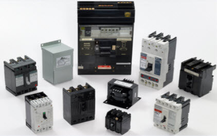
1. Miniature Circuit Breakers (MCBs) MCBs are small, compact breakers designed to protect low current circuits, typically up to 100 amps. They are used in residential and commercial settings to protect lighting and small appliances from overcurrents and short circuits. MCBs are known for their quick response and ease of resetting.
2. Molded Case Circuit Breakers (MCCBs) MCCBs are larger and more robust than MCBs, capable of handling currents up to 2,500 amps. They are used in commercial and industrial environments to protect larger loads and provide more advanced features such as adjustable trip settings and integrated metering.
3. Residual Current Circuit Breakers (RCCBs) RCCBs, also known as Ground Fault Circuit Interrupters (GFCIs), are designed to protect against earth faults and leakage currents. They are essential in environments where electrical safety is paramount, such as bathrooms, kitchens, and outdoor installations.
4. Air Circuit Breakers (ACBs) ACBs are used in high-current applications and can handle currents up to 6,300 amps. They provide protection for electrical distribution systems and are commonly found in industrial plants and large commercial buildings. ACBs offer advanced protection features, including adjustable trip characteristics and remote control capabilities.
Functions and Operation
LV breakers serve several key functions to ensure the safety and reliability of electrical systems:
1. Overcurrent Protection One of the primary functions of LV breakers is to protect circuits from overcurrents, which can cause overheating and damage to electrical components. Breakers achieve this by automatically disconnecting the circuit when the current exceeds a predetermined threshold.
2. Short Circuit Protection LV breakers protect against short circuits by rapidly disconnecting the circuit when a short circuit is detected. This prevents extensive damage to the electrical system and reduces the risk of fire.
3. Ground Fault Protection RCCBs and other specialized breakers provide ground fault protection by detecting leakage currents and disconnecting the circuit to prevent electric shock and fire hazards.
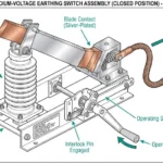
4. Isolation Breakers can also serve as isolating devices, allowing sections of an electrical system to be safely disconnected for maintenance and repairs.
Standards and Certifications
LV breakers must comply with various standards and certifications to ensure their safety and reliability. Some of the key standards include:
1. International Electrotechnical Commission (IEC) Standards IEC standards, such as IEC 60898 for MCBs and IEC 60947 for MCCBs and ACBs, provide guidelines for the design, testing, and performance of LV breakers.
2. Underwriters Laboratories (UL) Standards UL standards, including UL 489 for MCCBs and UL 1077 for supplementary protectors, are widely recognized in North America and ensure that LV breakers meet stringent safety and performance criteria.
3. National Electrical Code (NEC) The NEC provides guidelines for the installation and use of electrical equipment, including LV breakers, in the United States. Compliance with NEC standards is mandatory for electrical installations.
Advancements in LV Breaker Technology
1. Digital and Smart Breakers The integration of digital technology in LV breakers has led to the development of smart breakers that offer advanced monitoring and control capabilities. These breakers can communicate with building management systems, provide real-time data on electrical parameters, and enable remote operation and diagnostics.
2. Arc Fault Detection Advanced LV breakers now include arc fault detection technology, which can identify and interrupt dangerous arc faults that conventional breakers may not detect. This enhances safety by reducing the risk of electrical fires.
3. Enhanced Trip Units Modern MCCBs and ACBs feature enhanced trip units with adjustable settings, allowing for precise customization of protection parameters. These trip units can be programmed to respond to specific fault conditions, improving overall system protection.
4. Energy Efficiency Energy-efficient LV breakers are designed to minimize power losses and reduce energy consumption. These breakers contribute to the overall energy efficiency of electrical systems, supporting sustainability goals.
Applications of LV Breakers
LV breakers are used across a wide range of applications, including:
1. Residential In residential settings, MCBs and RCCBs protect electrical circuits in homes, ensuring the safety of occupants and preventing damage to appliances and wiring.
2. Commercial Commercial buildings, such as offices, shopping centers, and hotels, use MCCBs and ACBs to protect electrical distribution systems and ensure reliable power supply.
3. Industrial Industrial facilities, including factories and manufacturing plants, rely on robust LV breakers to protect machinery, equipment, and electrical infrastructure from overcurrents and short circuits.
4. Renewable Energy LV breakers are also used in renewable energy installations, such as solar and wind power systems, to protect electrical components and ensure safe operation.
Installation and Maintenance
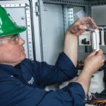
1. Proper Installation Proper installation of LV breakers is critical to ensure their effective operation. This includes selecting the appropriate breaker type and rating, following manufacturer guidelines, and adhering to relevant standards and codes.
2. Regular Maintenance Regular maintenance of LV breakers is essential to maintain their reliability and performance. This involves periodic inspections, testing, and servicing to identify and address any issues before they lead to failure.
3. Upgrading and Retrofits As electrical systems evolve, upgrading and retrofitting LV breakers may be necessary to enhance protection and meet changing requirements. This can involve replacing older breakers with modern, digital models that offer advanced features and improved performance.
Challenges and Considerations
1. Coordination and Selectivity Ensuring proper coordination and selectivity between breakers is crucial to prevent unnecessary power outages and ensure that only the affected circuit is disconnected during a fault. This requires careful planning and analysis of the electrical system.
2. Environmental Conditions LV breakers must be suitable for the environmental conditions in which they are installed. Factors such as temperature, humidity, and exposure to dust or corrosive substances can impact the performance and lifespan of breakers.
3. Compliance and Regulations Compliance with relevant standards and regulations is essential for the safe and legal installation of LV breakers. This includes adhering to national and international standards, obtaining necessary certifications, and following local electrical codes.
Future Trends
1. Integration with Smart Grids As smart grid technology advances, LV breakers will play a key role in enabling more efficient and reliable power distribution. Smart breakers will communicate with grid management systems to optimize power flow, reduce outages, and improve overall grid stability.
2. IoT and Connectivity The Internet of Things (IoT) is transforming the way electrical systems are monitored and managed. Connected LV breakers will provide real-time data on system performance, enabling predictive maintenance and enhancing overall operational efficiency.
3. Sustainability and Energy Management Sustainability is becoming increasingly important in the design and operation of electrical systems. LV breakers that support energy management and efficiency initiatives will be essential for reducing carbon footprints and achieving sustainability goals.
4. Enhanced Safety Features Future LV breakers will incorporate even more advanced safety features, such as improved arc fault detection, enhanced ground fault protection, and more sophisticated trip algorithms to ensure the highest levels of protection for electrical systems.
Conclusion
Low Voltage (LV) breakers are indispensable components in modern electrical systems, providing essential protection against overcurrent’s, short circuits, and other electrical faults. With advancements in digital technology, enhanced safety features, and integration with smart grids and IoT, the future of LV breakers promises to bring even greater reliability, efficiency, and safety to electrical installations across various sectors. Understanding the different types of LV breakers, their functions, standards, and latest technological developments is crucial for electrical professionals to design, install, and maintain robust and efficient electrical systems.

![Voltage Sag vs Interruption: Causes, Impact, and Fixes A plant can lose a production line from a blink of power, even when the lights come back almost at once. If you've seen a VFD trip, a contactor drop out, or a PLC reset after a split-second dip, you've seen power quality turn into a production problem. The issue is often not a full outage. It's a short voltage event that sensitive equipment can't ride through. Start with the basics, and the failure starts to make sense. What voltage sag and interruption mean A voltage sag is a short drop in RMS voltage below normal, usually to 10% to 90% of rated voltage, for 0.5 cycles up to 1 minute. In a 415 V system, a brief drop to 280 V or 250 V is a sag, not a blackout. Duration matters. If voltage stays low for more than a minute, that is usually undervoltage, not sag. A sag arrives fast, recovers fast, and can still stop a machine. This quick comparison makes the difference easier to see: EventWhat happensTypical durationVoltage sagVoltage drops but does not go to zero0.5 cycles to 1 minuteVoltage interruptionVoltage is zero or near zeroLess than 1 minuteUndervoltageVoltage stays below normal for longerMore than 1 minute An interruption is more severe because supply is lost completely, or almost completely, for less than a minute. If it clears in a few seconds after auto-reclosing, it is a momentary interruption. If it stays off beyond a minute, it becomes a sustained interruption. Why these events happen The most common cause is a fault on the power system. That could be a single line-to-ground fault, line-to-line fault, double line-to-ground fault, or a three-phase fault. When fault current rises, voltage drops across the network until protection clears the problem. If the fault is on your feeder, you may see a sag first and then an interruption when the breaker opens. If the fault is on another feeder from the same substation, your breaker may never trip, but your plant can still see a bus voltage dip. That is why equipment can trip even when "our feeder never opened." Large motor starting is another frequent cause. An induction motor can draw five to seven times full-load current during start. In a weak system, or where the motor is large compared with the transformer, that inrush can create a temporary sag. Transformer energization, capacitor switching, welding loads, arc furnaces, and sudden heavy loading can do the same. Why a tiny dip can stop a large machine > The main motor may ride through a sag, but the control power often won't. Older plants had more electromechanical loads, and many of them tolerated short dips. Modern plants rely on PLCs, VFDs, servo drives, electronic power supplies, sensors, relays, and SCADA. Those devices make automation possible, but many are more sensitive to voltage dips than the motor they control. Massive steel control panels and heavy machinery dominate the floor as overhead lights cast a chaotic, flickering glow. Sharp shadows and sparks suggest a sudden surge in the facility power grid. [https://user-images.rightblogger.com/ai/f382171e-d1b1-4320-b7eb-289d9b53ee27/industrial-factory-power-instability-93e17dc7.jpg] A short sag may not stop a spinning motor because inertia keeps it moving. Still, the contactor coil can drop out, the VFD can detect undervoltage, and the PLC power supply can reset. Once the control chain breaks, the process stops. In process plants, that can mean lost batches, reset time, scrap, labor loss, and delayed delivery. Magnitude and duration both matter. Some equipment can tolerate 80% voltage for five cycles, but not 40% for the same time. That is why ride-through curves matter, and why event recording matters too. Good monitoring tools, such as monitoring power quality with PME 2024 R2 [https://www.interestingautomation.com/schneider-pme-2024-r2/], help capture minimum voltage, duration, and affected phases. Practical ways to reduce voltage sag problems The most cost-effective fix starts with the weak point. If a 200 kW machine trips because a 230 V PLC supply resets, you usually do not need to protect the whole machine. You need to protect the control power. * Specify ride-through performance when buying critical PLCs, drives, relays, and controls. * Add a small UPS, DC backup, or capacitor ride-through module for control power. * Use a voltage sag compensator or dynamic voltage restorer for sensitive process loads. * Apply online UPS systems where transfer time cannot be tolerated. * Consider motor-generator or flywheel systems where short interruptions happen often. * Use static transfer switches only when the two sources are truly independent. Source quality matters too. Utilities reduce events with better protection coordination, faster fault clearing, line maintenance, tree trimming, and feeder automation. On the plant side, grid automation and fault visibility also help, which is why tools for using Easergy T300 for fault detection [https://www.interestingautomation.com/brief-explain-easergy-t300-features-benefits-and-complete-guide/] are relevant in systems that need faster disturbance response. Final thoughts A blink in voltage can do more damage to production than a short outage, because the failure often happens inside the control system before anyone sees a breaker trip. That is the core lesson behind voltage sag and interruption studies. The best fix is rarely the biggest one. Find what actually trips, measure how deep and how long the event lasts, and protect the most sensitive part first. A brief dip should not turn into hours of downtime.](https://www.interestingautomation.com/wp-content/uploads/2026/05/Voltage-Sag-vs-Interruption-Causes-Impact-and-Fixes-150x150.jpg)
![Why MV Switchgear Fails: 5 Causes That Lead to Major Faults A 36 kV switchgear panel can sit closed for two years, carry load without complaint, and still fail on the one day you need it to clear a fault. That is the risk hiding behind a quiet panel. If the breaker won't trip, if protection doesn't detect the fault, or if insulation breaks down inside the cubicle, the result can be fire, arc flash, equipment loss, and a hard production stop. The real job is not waiting for failure and reacting later. It is spotting the warning signs before the panel runs out of margin. What counts as a switchgear failure Not every defect in a medium-voltage panel is a true failure. That distinction matters because reliability studies do not count every bad lamp, loose label, or minor nuisance the same way they count a breaker that won't trip. IEC 62271-1, clause 3.1.12, defines a major failure as a failure of switchgear and controlgear that causes the loss of one or more fundamental functions. It also says a major failure leads to an immediate change in system operating conditions, such as backup protection having to clear a fault, or forces unscheduled removal from service within 30 minutes. Major failures affect the core job of the panel In plain language, a major failure means the switchgear can no longer do one of its main jobs. Those jobs include switching, protection, monitoring, and control. If a fault occurs and the protection system does not detect it, that is a major failure. If the relay sends a trip command and the vacuum circuit breaker stays closed, that is also a major failure. The same goes for a situation where one bus section fails and the plant has to shift supply to another bus to keep running. The standard's wording about "immediate change in operating conditions" is useful because it points to real plant behavior, not theory. When primary protection fails and backup protection has to step in, the system has already moved into an abnormal state. If a breaker will not close because of a spring problem and must be removed from service at once, the equipment has lost its reliability. Minor failures are different, even if they still need attention A minor failure is anything that does not take away those core functions. An LED indication lamp that has gone dark is annoying, but it does not stop the panel from switching or protecting the system. A cosmetic defect may need correction, but it does not belong in the same category as a breaker mechanism that sticks. That distinction helps when you look at failure data. Most reliability studies focus on major failures, because those are the events that threaten safety, uptime, and equipment life. > A panel does not become dangerous only when it burns. It becomes dangerous the moment it can no longer switch, protect, or isolate a fault as intended. The five failure modes behind most serious problems Across published guidance and field experience, the same trouble spots keep showing up in MV switchgear. Insulation breakdown and mechanical faults sit near the top, while overheating, environmental stress, and aging keep chipping away at the system until something gives. A single medium voltage switchgear panel stands inside a clean and brightly lit industrial facility. [https://user-images.rightblogger.com/ai/f382171e-d1b1-4320-b7eb-289d9b53ee27/medium-voltage-switchgear-panel-dc9d5203.jpg] This quick summary helps frame where the risk usually sits: | Failure mode | Typical share or impact | Common triggers | Best early warning | | | | | | | Insulation failure | About 20% to 30% of failures | Partial discharge, insulation defects, contamination | PD testing or continuous PD monitoring | | Internal arc | Less about share, more about severity | Insulation breakdown, loose parts, human error, foreign objects | Arc detection plus proper panel design and rating | | Busbar and connection overheating | Major contributor within remaining failures | Poor joints, high contact resistance, loose terminations | Thermal inspection or continuous temperature monitoring | | Environmental and aging effects | Significant long-term driver | Moisture, dust, corrosion, seal failure, material degradation | Inspection, humidity monitoring, life assessment | | Mechanical failures | About 30% to 40% of failures | Trip coil issues, dry lubrication, worn parts, weak spring energy | Breaker monitoring and functional testing | The headline is simple. A switchgear failure usually starts as a small loss of margin, then turns into a major event when nobody is watching. Insulation failure usually starts where you can't see it Insulation failure is one of the biggest reasons MV switchgear fails. The hard part is that the panel can look healthy from the outside while the weakness grows inside cable insulation, busbar insulation, or instrument transformer resin. Partial discharge is small at first, then destructive Partial discharge starts when electrical stress concentrates inside tiny voids, impurities, or defects within insulation. In a cable, for example, a manufacturing void or a badly prepared termination can create a weak point. Stress collects there because the local dielectric strength is lower. Once the stress exceeds what that spot can withstand, a localized discharge starts. It is called "partial" because the discharge does not bridge the full insulation path at first. Still, the damage does not stay small. Repeated discharges eat away at the insulation until a much larger fault develops. A wood beam with termites offers a good comparison. The outside may still look sound, while the inside has already lost strength. By the time the damage is visible, the collapse is close. In MV panels, partial discharge often shows up in cable terminations, cable insulation itself, CT and VT epoxy insulation, and insulated busbar systems. The danger is that it rarely gives an obvious warning unless you are looking for it. For a broader research view, the review of medium-voltage switchgear fault detection [https://www.mdpi.com/1996-1073/15/18/6762] covers common detection methods and fault behavior in more detail. Periodic partial discharge testing helps, but it has a limit. You only see the panel at the moment of the test. Continuous monitoring fills the blind spot between maintenance visits. That difference matters more as the switchgear ages. Internal arc is where hidden weakness becomes immediate danger Internal arc is one of the worst events that can happen inside switchgear because it combines heat, pressure, smoke, and metal vapor in a confined space. It is not the same thing as a normal short circuit. An internal arc is a fault that develops inside the enclosure and puts people nearby at direct risk. Insulation failure can trigger it. So can a loose connection, a dropped tool, a foreign object left behind after maintenance, or simple human error. A screwdriver bridging two phases is enough to turn a routine task into a violent event. Besides fire damage, the smoke from an internal arc is hazardous on its own. That is why this topic is not only about asset protection. It is also about human safety. Modern panels may include arc detection systems that watch for both light and current. When they detect an arc, they send a trip command in milliseconds. It also pays to check whether the panel has been tested for internal arc classification, because that tells you how the equipment is expected to behave during this kind of fault. Heat at joints and contacts can undo a good panel Every electrical joint carries some risk. If the connection is poor, resistance rises. When current keeps flowing through that resistance, I squared R losses turn into heat, and heat becomes the start of the next failure. This issue appears again and again at busbar joints, cable terminations, breaker contacts, and earthing connections. The busbar connection between two panels is a common weak point. So is the cable end where termination quality depends on careful stripping, clean surfaces, correct materials, and proper tightening. In withdrawable breakers, primary contact engagement needs extra attention because poor seating can cause local hot spots. The physics is simple, but the effect is expensive. A small increase in contact resistance can push the temperature high enough to damage insulation, oxidize surfaces, weaken spring pressure, and set up the next arc fault. That is why overheating is a recurring theme in switchgear failure analysis, including this overview of switchgear failures and solutions [https://blog.exertherm.com/causes-of-switchgear-failures-and-solutions]. Good workmanship cuts most of this risk at the start. Joints need the right preparation, the right torque, and the right method from the manufacturer. After installation, thermal checks matter. A handheld IR inspection helps during rounds, but large sites with many panels often need more than occasional scans. Fixed thermal sensors on critical joints can track temperature all day and flag a problem before the panel forces a shutdown. Age and environment wear down the margin of safety Switchgear does not fail only because something was assembled badly. Time and environment also wear down the panel, even when operation looks normal. A typical service life is often described as about 25 to 30 years, though real life depends on duty, environment, maintenance, and design. Once equipment gets deep into that age range, the risk rises. Insulation can crack. Corrosion can creep across sheet metal and hardware. Seals can weaken in gas-filled compartments. Contacts wear. Springs lose strength. Materials that looked stable for years start to drift out of their original condition. Environmental stress speeds that process up. Moisture is a common problem because it lowers insulation resistance and can help contamination become conductive. Dust does the same thing when it settles where it should not. Some reported failure summaries tie a large share of busbar trouble to moisture and dust exposure, and this medium-voltage switchgear problem summary [https://www.green-energy-elec.com/common-problems-in-medium-voltage-switchgear/] highlights that pattern clearly. The fix depends on the site. Air-insulated panels in humid, dusty areas need more cleaning and inspection. Higher IP ratings help when the environment is harsh. In some applications, enclosed technologies such as GIS or solid-insulated systems reduce exposure. Humidity sensors inside selected panels also help, because they warn you when the room condition and the cubicle condition are drifting apart. Mechanical failures stop the breaker when it matters most Mechanical trouble is often the biggest single contributor to MV switchgear failure. That makes sense because a fault may be detected perfectly, yet the system still fails if the breaker mechanism cannot move. A breaker that has stayed closed for two years can look healthy, but that does not prove it will trip on demand. The trip coil may be open or shorted. Lubrication may have dried out or picked up contamination. Stored-energy springs may have weakened. Linkages may seize. Contacts may be worn. Any one of those problems can turn a valid trip command into a non-event. That is the nightmare scenario in a live plant. Fault current continues to flow because the breaker remains closed. Backup protection may clear the fault later, but the delay can mean heavier equipment damage, a wider outage, and greater risk to people nearby. Routine maintenance helps because it proves the mechanism can still move. Still, periodic checks have gaps. A breaker can pass a test in January and develop a mechanical issue in March. That is why breaker monitoring is gaining ground. Modern systems can track operating count, contact wear, gas or pressure status where relevant, opening and closing speed, and other health indicators that point to a weakening mechanism. For teams that already use connected diagnostics on breakers, tools such as a Pact series breaker diagnostic and testing interface [https://www.interestingautomation.com/schneider-electric-service-interface-kit-pact-series-circuit-breakers-installation-compatibility-expert-review/] show how live measurements and event data can shorten troubleshooting time and expose developing faults before a trip failure happens. > A breaker is not reliable because it stayed closed. It is reliable because you have evidence that it can still open. Why monitoring beats calendar-based maintenance alone Traditional maintenance still matters. Panels need cleaning, inspection, tightening, lubrication, and testing. Yet calendar-based maintenance only gives you snapshots. It cannot tell you what happened between visits. Monitoring changes that. A continuous system can watch temperature rise at a joint, catch partial discharge activity, track humidity inside a cubicle, and record breaker operation data around the clock. It also makes condition-based maintenance possible. Instead of opening equipment on a fixed calendar, you act when data shows the condition is changing. That approach is often the difference between "repair after failure" and "intervene before failure." On new switchgear, you may not need every sensor from day one. On older panels, on hard-worked breakers, or across a large fleet, the case for monitoring becomes much stronger. A plant-wide supervision layer also helps because raw data is not enough by itself. Operators need one place to see alarms, status changes, and events in context. Platforms focused on real-time monitoring with Schneider EPAS [https://www.interestingautomation.com/schneider-electric-epas/] show why visibility matters when a feeder trips or a breaker changes state. Faster fault isolation starts with seeing the right information at the right time. Final thoughts The most dangerous switchgear failures do not start with a dramatic event. They start with a missed warning, a weak joint, a dry mechanism, or insulation that is breaking down in silence. If there is one takeaway to keep, it is this: reliability needs proof. A breaker that has been closed for two years is only comforting when you know it can still trip today, and the rest of the panel can still do its core job when the fault arrives.](https://www.interestingautomation.com/wp-content/uploads/2026/05/Why-MV-Switchgear-Fails-5-Causes-That-Lead-to-Major-Faults-150x150.jpg)