Meters, relays, and a control center don’t care how smart they are if they can’t talk. In a real substation, each device may speak a different “language,” and the control room still expects one consistent view.
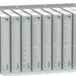
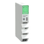
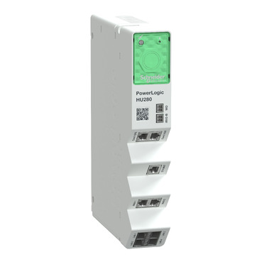
That’s where PowerLogic HU280 communication protocols matter. The HU280, used as a communication gateway module in the PowerLogic T500 ecosystem, helps move data and commands between field devices and upstream systems. In practice, it’s the piece that makes telemetry, events, and remote control work across mixed equipment.
This post stays practical. It explains the four protocols you’ll run into most with HU280 projects (IEC 60870-5-101, IEC 60870-5-103, IEC 60870-5-104, and DNP3), the everyday difference between serial and Ethernet paths, and how to pick the right protocol for a substation or industrial power setup without guessing.
PowerLogic HU280 communication protocols, the supported options and what each one is best at
Most projects don’t start with “Which protocol is best?” They start with “What does the control center already support?” That single constraint often decides everything. The HU280 sits in the middle and aligns the field side with the SCADA or RTU side.
At a high level, the four protocols in scope here map to common needs:
- IEC 60870-5-101 (IEC 101): A classic choice for serial communications, especially where legacy IEDs and older RTUs still exist.
- IEC 60870-5-104 (IEC 104): Same IEC 60870 family, but designed for TCP/IP networks. It fits modern Ethernet-based substation networks.
- IEC 60870-5-103 (IEC 103): Often used to read data from certain protection relays and bay devices where 103 is the native protocol.
- DNP3: Common in North American utility telemetry and SCADA integration, both for polling and for unsolicited event reporting.
If you need the vendor’s reference set for HU280 features and protocol behavior, keep the PowerLogic HU280 user manual close during design and commissioning. It’s the document that helps settle details like supported roles, channel types, and protocol-specific settings.
One more point matters early: some protocol stacks run as client or server. In plain terms, the client usually starts the conversation, and the server answers. However, “client” doesn’t mean “more important.” It only describes who initiates and who listens.
The table below gives a quick, field-focused view before we get into the details.
| Protocol | Most common transport | Typical direction | What it’s best at |
|---|---|---|---|
| IEC 101 | Serial (RS232/RS485) | Polling plus events | Legacy links, simple serial integrations |
| IEC 104 | Ethernet (TCP/IP) | Session-based over IP | Modern SCADA over routed networks |
| IEC 103 | Serial (often) | Usually gateway reads IED | Protection relay data access |
| DNP3 | Serial or Ethernet | Polling and unsolicited | Utility telemetry and controls |
If your SCADA mandates a protocol, start there. Protocol “preference” doesn’t beat an interface requirement.
IEC 101 vs IEC 104, same family, different networks
IEC 101 and IEC 104 look similar on paper because they share the same application concepts, like points, causes of transmission, and control commands. The big difference is the network layer.
IEC 101 typically runs over serial media, such as RS232 or RS485. That makes it a common fit when you inherit older wiring, leased lines, or long-standing relay integrations that were never upgraded to Ethernet. Serial also appeals when the site has strict segmentation and you want a “hard” boundary between networks.
IEC 104 runs over TCP/IP. In practice, that means Ethernet switches, IP addresses, routing, and firewall rules become part of commissioning. The upside is scale. IP networks support more flexible topologies, simpler integration to modern control centers, and easier transport over WAN links when engineered correctly.
Client and server roles also get clearer over IP:
- In server mode, the HU280 listens for an inbound connection, then responds to the control center.
- In client mode, the HU280 initiates the connection toward a listening SCADA endpoint or a head-end gateway.
Everyday impact: server mode usually requires inbound firewall openings to the HU280, while client mode often avoids inbound rules because the HU280 “calls out.” That one choice changes the work with IT, and it also changes which side needs the stable IP address.
For physical installation considerations that affect comms stability, the PowerLogic HU280 installation guide is the document most techs reference while landing wiring, checking port status, and confirming the module is seated and powered correctly.
IEC 103 and DNP3, where they fit in real substations
IEC 103 shows up in a specific place: the relay and bay-device layer. When a protection relay family supports IEC 103 natively, reading it through an IEC 103 client can be the most direct option. In practical terms, IEC 103 helps collect indications, measurements, and events from devices that were designed around that protocol.
A common planning mistake is assuming IEC 103 behaves like IEC 101 with different point labels. It doesn’t. IEC 103 mappings can be more device-specific, and the gateway often plays the “active” role (client) that requests and organizes data from the IED. That’s why early point-list validation matters. You want to confirm what the relay actually exposes before you promise points to SCADA.
DNP3 fits differently. In the US, it’s still a default answer for utility telemetry because many head-ends, RTUs, and legacy systems standardize on it. DNP3 also has a long history with event buffering and time-tagged reporting. That’s useful when the comm link drops and later recovers.
Here’s a quick pick guide that matches how projects usually get decided:
- If the control center requires DNP3, choose DNP3 and design addressing and event classes around the head-end standard.
- If the site standard is IEC interoperability, pick IEC 101 for serial constraints or IEC 104 for IP networks.
- If you must talk to IEC 103 devices, plan for IEC 103 client behavior and confirm relay support early.
For broader system context, including how substation controller platforms position gateway functions, the PowerLogic T500 platform user manual is a helpful cross-reference when you need to align HU280 comms with overall T500 architecture and engineering workflow.
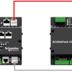
How the HU280 connects, serial, TCP, and UDP without the confusion
Protocol selection is only half the job. The other half is choosing the connection type, then wiring and securing it so it behaves the same on day 200 as it did on day 1.
In HU280 projects, the physical and transport choices usually fall into three buckets:
Serial (RS232/RS485) for direct, low-level wiring to devices and legacy equipment.
TCP over Ethernet when you need reliable delivery, session control, and clear firewall behavior.
UDP over Ethernet when a service uses datagrams and you accept that delivery is not guaranteed.
Techs see the difference right away on site. Serial problems show up as parity errors, framing errors, or silent ports. IP problems show up as link lights, VLAN issues, wrong gateways, blocked ports, and mismatched client-server roles.
Distance and noise also matter. Serial can run long distances in the right mode (especially RS485), but it demands correct termination and grounding habits. Ethernet gives clean troubleshooting tools like ping and port counters, but only if the network is designed and documented.
Serial links (RS232 and RS485), when simple wiring still wins
RS232 and RS485 often get lumped together as “serial,” yet they behave very differently.
RS232 is typically point-to-point. It’s straightforward when you have one gateway port and one device. Cable lengths are limited, and noise can be an issue in high EMI areas, so good routing and shielding practices matter.
RS485 supports multi-drop wiring in many deployments. That makes it useful when several IEDs share one bus. It also tends to handle electrical noise better than RS232 when installed correctly.
Most serial commissioning failures come from small mismatches, not broken hardware. A short on the pair, a swapped polarity, or a missing termination can waste hours. Before you blame the protocol stack, confirm the basics:
- Match baud rate and parity on both ends.
- Confirm the correct 2-wire vs 4-wire RS485 mode when applicable.
- Use proper termination at the ends of the RS485 bus, not at every device.
- Keep shield grounding consistent with the site standard, avoid creating ground loops.
- Verify device addressing (IEC and DNP3 both depend on clean addressing).
Also remember that serial success depends on discipline. If someone changes one relay from 9600 8E1 to 19200 8N1 during a retrofit, your gateway won’t “figure it out.”
TCP and UDP channels, called vs calling, and why it changes your setup
Ethernet setups fail for a different reason: the physical wiring is fine, but the session roles are wrong.
Many gateways describe TCP behavior using terms like:
- Called: the device listens and accepts inbound connections.
- Calling: the device initiates outbound connections.
- Both: it can do either, depending on configuration.
In everyday terms, “called” means you must route traffic to the HU280 and allow inbound ports through firewalls. “Calling” means the HU280 needs a route out and the far end must listen. As a result, calling mode often works better across segmented networks because it reduces inbound exposure.
UDP adds another wrinkle. It has no session handshake, so packets can arrive out of order or not at all. That doesn’t mean UDP is “bad,” but it does mean troubleshooting changes. You focus on ACLs, QoS, and packet captures, not connection state.
A practical rule helps: if the protocol expects reliable delivery and ordered messages, TCP fits. If the service is designed around light, periodic datagrams, UDP can fit, but you must accept stricter network discipline.
For broader product and deployment context around T500 communications modules, the PowerLogic T500 catalog provides a useful reference when you’re aligning physical ports, module options, and overall comms planning.
Configuration basics that prevent the most common protocol problems
Configuration mistakes usually look like “protocol issues,” but the root cause is often simpler: wrong role, wrong addressing, or a channel that never got built.
A good workflow starts with one assumption: nothing works until you define it. In many deployments, no default protocol channels come pre-set for your exact job. You build the channels you need, map data, then test end-to-end.
Teams also benefit from separating two tasks:
- Network access setup: set IP addresses, routing, and allowed services so you can reach the device safely.
- Protocol engineering: define channels, roles, addressing, and point mapping.
Many sites use Easergy Builder as the engineering tool for configuration and project management. Even if you only change one channel, keep the project files controlled and backed up. Otherwise, the next tech has to reverse-engineer settings from the live unit.
Documentation isn’t paperwork for its own sake. A single page that lists IPs, ports, roles (client or server), and addressing can cut troubleshooting time in half during an outage.
Build your channels first, then map data, then test end-to-end
A clean workflow keeps you from chasing ghosts. The sequence below matches how successful commissioning usually goes:
- Pick the protocol based on the upstream system requirement (SCADA, RTU, DMS).
- Choose the interface (serial or Ethernet) based on available wiring and network policy.
- Set the role (client/server, calling/called) so the connection direction is unambiguous.
- Configure addressing (station addresses, link addresses, point indexes) to match the other end.
- Map data points into clear groups (status, analogs, counters, commands).
After that, test like an operator, not like a programmer. You want proof that the full chain works, not just that a port is open.
A simple acceptance checklist helps:
- Confirm the session connects and stays stable.
- Read a few known values and compare with the relay or meter front panel.
- Verify timestamps and event order where the protocol supports it.
- If controls are allowed, run one controlled command during a safe window.
- Check that alarms and events show up in the right place upstream.
Don’t scale to 20 devices until one device works perfectly. Repeatable success beats fast progress.
Reliability and cybersecurity settings you should not skip
Gateways sit at a boundary, so basic security controls matter. The goal isn’t to make the system hard to use. The goal is to make it predictable.
Start with the simplest steps:
Limit open ports to only what the protocol needs. If the site only uses IEC 104, don’t leave extra services exposed. Next, restrict allowed IP addresses where the platform supports it, so only the SCADA servers or engineering workstations can connect. Segmentation also helps. A dedicated OT VLAN with controlled routing reduces accidental exposure.
The HU280 platform family is described with built-in cybersecurity capabilities in vendor documentation, including security management features aligned with substation needs. Use that as a reason to set sane defaults, not as a reason to skip design review.
Reliability planning is similar. Some installations use the gateway as a standalone device, while others plan a backup gateway role. In practical terms, backup means you design for failover, keep configurations aligned, and test the switch-over path before it’s needed. A backup that nobody has tested is only comforting on paper.
Conclusion
Choosing among PowerLogic HU280 communication protocols gets easier when you make one decision first: match the control center requirement. After that, pick IEC 101 when you must stay on serial, pick IEC 104 when you’re on IP networks, use DNP3 when utility telemetry demands it, and plan for IEC 103 when you need to read IEC 103 IEDs.
Next, list every device in the path and confirm what each side supports. Then build and test one channel at a time before you scale up. When the whole site shares one “language,” the control room stops guessing, and operations get calmer fast.