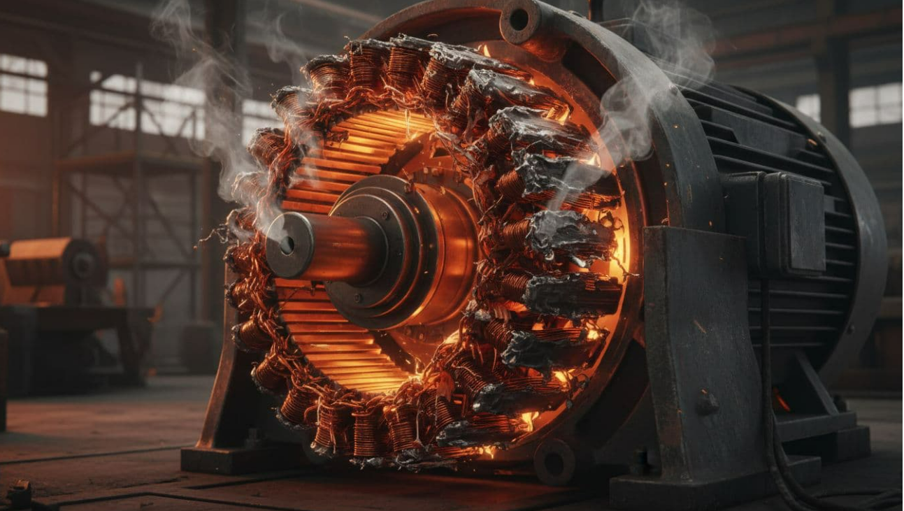
Medium voltage motors usually run above 1,000 V, and they drive some of the hardest-working loads in a plant. Think pumps, fans, compressors, crushers, and mills. When one of these motors fails, the damage rarely stays small. A single fault can burn windings, stop a process line, or raise fire and arc-flash risk in seconds.
That’s why medium voltage motor fault protection has to do more than trip on high current. It needs to spot fast faults, track heat, and separate normal starting stress from real danger. In the sections below, you’ll see the common fault types, the core relay functions, how engineers choose settings, and the mistakes that often lead to nuisance trips or missed faults.
The faults that medium voltage motor protection has to catch
Protection starts with a simple question: what can actually go wrong? In the field, faults show up as rising heat, vibration, repeated starts, odd current balance, or a sudden shutdown. Because MV motors carry more energy than low-voltage units, a fault can move from minor to destructive very fast.
Overload, locked rotor, and stall faults that build heat fast
An overload means the motor works above its safe load for too long. Current may not look extreme at first, but heat keeps rising. Over time, insulation ages faster, and the motor life shrinks.
A locked-rotor or stall event is more severe. In a locked-rotor case, the shaft can’t turn when power is applied. In a stall case, the motor was turning but then jams or can’t keep moving the load. In both cases, rotor and stator heating climbs fast, especially during starting.
That’s why overload protection usually uses time, while stall and locked-rotor protection act much faster. In the plant, operators may notice a hot smell, a slow start, or repeat trips after a jammed conveyor or stuck pump.
Short circuits, phase faults, and ground faults that need instant action
Some faults don’t build slowly. They hit like a hammer. Phase-to-phase faults, phase-to-ground faults, and internal winding faults can create very high current and tear through insulation in moments.
Ground-fault protection often uses zero-sequence or residual sensing to catch current leaking to ground. For internal faults inside the motor zone, differential protection usually gives the fastest and most sensitive response. It compares the current entering the motor with the current leaving it. If those values don’t match as they should, the relay sees a fault inside the protected zone.
Short-circuit damage often leaves little room for error. Quick clearing limits burned copper, core damage, and downtime.
Voltage imbalance, undervoltage, and other power quality problems
Not every motor problem starts as a hard fault. Poor supply quality can hurt the motor even before the current looks alarming. Voltage unbalance causes uneven phase currents, and that extra imbalance heats the rotor. Low voltage can also force the motor to draw more current to hold torque.
Phase loss, voltage sags, and harmonics add more stress. A motor may still run, but it runs hotter and less smoothly. In the field, it can look like poor acceleration, vibration, or nuisance trips under normal load.
If insulation health is already weak, these stresses matter even more. Routine checks, such as insulation resistance tests on motors can help confirm whether the motor still has margin left.
The core protection functions every medium voltage motor scheme should consider
A good protection scheme uses layers. One layer handles major faults. Another watches the heat. A third layer checks supply quality and starting behavior. The exact package depends on motor size, duty cycle, starting method, and how much process risk the plant can accept.
Overcurrent and thermal protection form the basic safety layer
The first layer is usually overcurrent protection. In plain terms, that means the relay trips when the current gets too high. Instantaneous overcurrent, ANSI 50, reacts to very high fault current. Time overcurrent, ANSI 51, allows short overloads but trips if the current stays high too long.
Thermal protection goes a step further. It estimates motor heating over time, often with a thermal model, and it may also use RTDs or stator temperature sensors. This matters because a motor can overheat even when the current is not extreme. Poor cooling, repeated starts, blocked airflow, or high room temperature can push the motor past safe limits.
In other words, current alone doesn’t tell the full story.
Differential, ground-fault, and negative-sequence protection add deeper coverage
Differential protection, ANSI 87, works like a balance check. It compares what goes into the motor with what comes out. If the difference is too large, the fault is likely inside the motor zone, and the relay trips fast. For MV motors, this is one of the strongest tools for internal fault protection.
Ground-fault protection, often 50N or 51N, watches for current leaking to earth. It can catch insulation failure early, before a larger fault grows.
Negative-sequence protection is also important. In simple terms, it looks for unbalanced current. That imbalance produces rotor heating, even when the average current seems acceptable. Because rotor bars don’t forgive extra heat, this function often prevents damage that operators might not spot in time.
The best relay settings won’t help if CT polarity is wrong or the trip path doesn’t work.
CT quality matters here. Saturation, wiring errors, or bad testing can cause false operation or blind spots.
Underpower, start supervision, and restart limits help protect the process, too
Protection is not only about short circuits. It also protects the machine system around the motor. Underpower can show that a pump has lost load, a belt has broken, or a process has run dry. That protects the driven equipment as much as the motor.
Start supervision looks at long acceleration time, incomplete start, and too many starts in a set period. Those functions help prevent damage to couplings, shafts, and pumped systems. They also keep operators from trying repeated restarts that slowly cook the rotor.
For large motors, this process-focused layer is often what separates a safe shutdown from a long outage.
How engineers choose relay settings without causing false trips
Relay settings must walk a fine line. They have to trip during real faults, but still allow normal starting and running. That means engineers need real motor data, real load behavior, and clean coordination with upstream devices.

This quick table shows the inputs that matter most.
| Input | Why it matters | Typical effect on settings |
|---|---|---|
| Rated voltage and FLA | Sets the normal operating base | Defines pickup references |
| Starting current | Shows expected inrush | Prevents false trips during start |
| Start time | Shows how long high current lasts | Shapes, stall, and acceleration limits |
| Allowable stall time | Protects rotor and stator heat limits | Sets fast trip boundaries |
| Insulation class and sensors | Shows thermal margin | Adjusts thermal model and alarms |
| Driven load type | Explains torque demand | Changes start and overload behavior |
The result is never one-size-fits-all.
Start with the motor data, starting method, and load profile
The first step is always the motor nameplate and test data. Engineers check rated voltage, full-load current, starting current, start time, allowable stall time, service factor, sensor type, and the driven load.
The starting method changes everything. An across-the-line start creates a high inrush and fast thermal rise. A VFD changes current shape and may reduce starting stress. If the motor uses medium voltage soft starters for motors, the relay must expect a different acceleration profile than a full-voltage starter.
Load profile matters too. A fan usually unloads at the start. A conveyor, crusher, or positive-displacement pump may not.
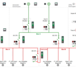
Coordinate relays, fuses, and breakers so the right device trips first
Selective coordination means the closest protective device should clear the fault first. That keeps the outage small. Engineers use time-current curves to make sure the motor relay, upstream breaker, and any fuses don’t trip out of order.
In many schemes, short-circuit clearing depends on fuses or breakers, while the motor relay handles thermal and system conditions. Broad IEEE and IEC guidance still points to the same goal in March 2026: enough separation to avoid overlap, but not so much delay that damage grows. A common coordination margin is about 0.3 to 0.4 seconds, though breaker speed and CT accuracy can change that.
For phase overcurrent, settings often land around 1.35 to 1.5 times motor current. Still, that’s only a starting point. The final value depends on the actual start profile and service duty.
Test CTs, sensors, and trip logic before trusting the scheme
Commissioning is where a good design proves itself. Injection testing checks that the relay sees the right current and trips at the right level. RTD checks confirm that temperature inputs are real. Breaker trip tests prove the output chain works from relay contact to device action.
Differential schemes need extra care. The motor cables must sit inside the protected zone, and CT polarity must be correct. Modern guides also stress full loop testing, not only relay bench checks.
If a thermal or overload alarm keeps returning, maintenance teams should compare relay data with starter behavior. In some cases, a fault history like ATS22 OLF overload fault troubleshooting helps narrow the cause faster.
Best practices that improve medium voltage motor fault protection over time
Protection should improve with the plant, not stay frozen after startup. As of March 2026, multifunction digital relays keep adding better waveform capture, event records, CT supervision, predictive alarms, and IEC 61850 communication. Those features help, but only when teams use them with discipline.
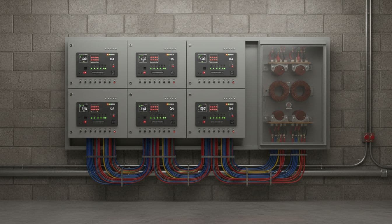
Use multifunction digital relays, but keep the logic simple and documented
One relay can now handle overcurrent, thermal, start limits, ground fault, negative sequence, event logs, and alarms. That reduces hardware and gives maintenance better fault records.
Still, too much custom logic creates trouble later. If only one engineer understands the setting file, the protection becomes fragile. Clear trip labels, saved settings, and simple cause codes help technicians respond fast during an outage.
Review trip records and motor history to catch trouble early
Trip data is not just for post-failure blame. It’s an early warning system. Repeated starts, a slow rise in stator temperature, or a small but steady current unbalance can point to trouble weeks before a hard fault.
Good maintenance teams review event logs, start counters, RTD trends, and breaker operations together. That gives context. A single trip may be noise. A pattern is a message.
Conclusion
Medium voltage motor protection works best when it uses layers. Fast fault functions clear destructive events, thermal tools watch heat, and careful settings let the motor start and run without false trips. Regular testing closes the loop because even the best relay can’t protect a motor through bad wiring or a failed trip circuit. Start with the real motor and the real process risk, then build medium voltage motor fault protection that catches faults quickly, tracks heat honestly, and stays dependable in daily operation.