Picture power leaving a plant like water leaving a dam. It has to cross long distances before it reaches homes, shops, and factories. A voltage transformer in substation systems changes that electrical “pressure” so the trip stays efficient and the final supply is safe to use.
Here, the term uses the common substation meaning, the transformer that changes system voltage for transmission and distribution. It also helps the station feed sensible voltage levels to metering and protection equipment. The basics are simple once you see the path.
What a voltage transformer in substation work really does
A substation transformer raises or lowers voltage between one part of the grid and the next. Near generation, it often raises voltage so power can travel far with less loss. Closer to users, it lowers voltage again so feeders and local equipment can handle it.
Most substations use three-phase transformers, because grid power is usually three-phase. Their size can vary a lot, from units that serve a small distribution yard to massive transmission transformers weighing many tons. If you want a broader picture of the levels around them, this guide to understanding MV voltage levels helps place the transformer in the wider network.
Why power companies change voltage before electricity travels
The reason is simple physics. For the same power, higher voltage means lower current. Lower current means less heat in conductors, because line losses rise fast as current rises.
Think of moving the same amount of water. Higher pressure can move it with less bulk flow. Electricity isn’t water, of course, but the picture helps. By stepping voltage up before long transmission and down before local delivery, utilities waste less energy and keep service more stable.
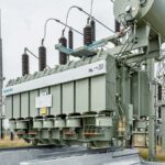
Where the transformer sits in the substation and what it connects to
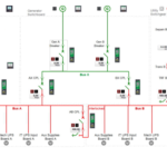
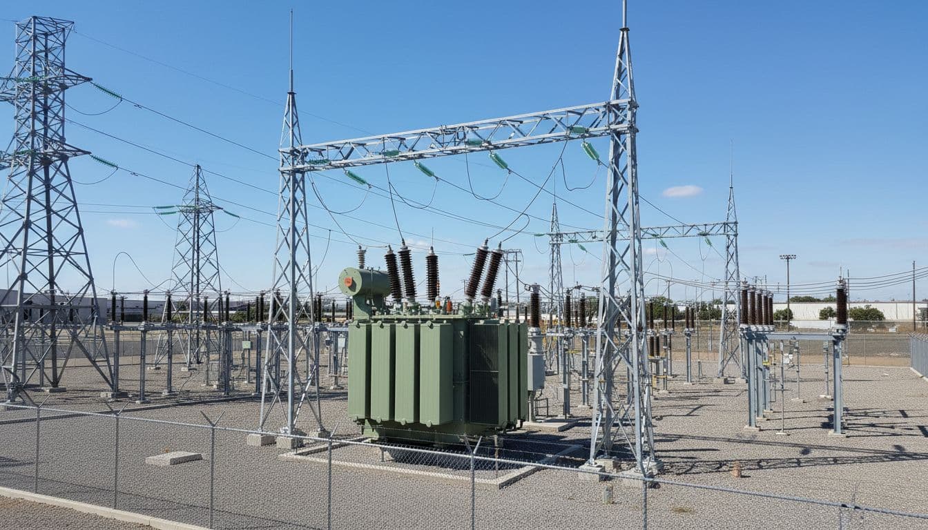
In a substation yard, the transformer usually sits between incoming and outgoing parts of the system. One side ties to transmission lines or a higher-voltage bus. The other side feeds a lower-voltage bus, outgoing feeders, switchgear, breakers, and cables. Nearby, relays and control panels watch its condition and respond to faults.
How the transformer changes voltage, step by step
A transformer works because alternating current keeps changing. When AC flows in the primary winding, it creates a changing magnetic field in the steel core. That changing field passes through the secondary winding and induces a new voltage there. That’s Faraday’s law in plain English.
The key rule is the turns ratio. If the primary has more turns than the secondary, the secondary voltage goes down. If the secondary has more turns, the voltage goes up. In short, V1 divided by V2 equals N1 divided by N2, which means voltage follows the winding-turn ratio.
Primary winding, core, and secondary winding in plain English
The primary winding is the input coil. The core is the metal path that guides magnetic flux. The secondary winding is the output coil. Those three parts do the main job.
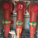
Other parts support them. Insulation keeps the windings apart. Bushings let conductors enter and leave the tank safely. Cooling oil, radiators, or fans carry away heat so the transformer doesn’t cook itself from the inside.
Step-up and step-down action with a simple example
A generator might produce power at 11 kV. A nearby substation transformer can raise that to 220 kV for transmission. Later, another substation lowers it to medium-voltage distribution levels, then another step brings it down again for building use.
So, the transformer acts like a pressure-changing station on a long route. It doesn’t create power. It changes the voltage level so the grid can move that power where it’s needed.
Main types used in substations and when each one is chosen
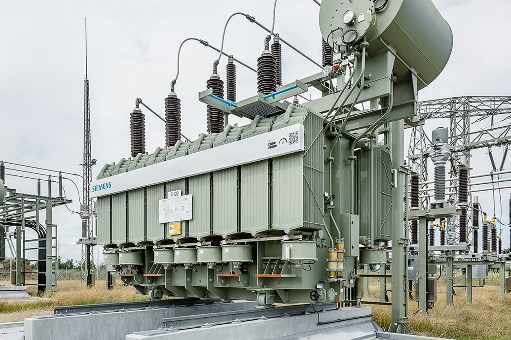
The most common choice is the power transformer. It’s the large unit that handles bulk energy transfer between voltage levels. Transmission substations use very high ratings, while distribution substations use lower ranges that feed towns, campuses, and industrial sites. Many of these units are three-phase and oil-filled.
Some substations also use special designs. Rectifier transformers serve AC to DC conversion, often in HVDC links or heavy industrial processes. Phase-shifting transformers help control power flow across parallel paths and support grid stability when one corridor carries too much load. For a broader technical overview, substation transformers explained offers added context.
Why these transformers matter for safety, reliability, and grid control
Without a voltage transformer in substation systems, losses would climb, equipment would see the wrong voltage, and power quality would suffer. The transformer is one of the quiet giants of the grid. When it works well, almost nobody notices.
How transformers support metering and protective relays
Meters, relays, and automation systems need controlled, usable signals. The substation arrangement around the main transformer makes that possible. Protection schemes depend on accurate sensing, fast trips, and clean coordination. That’s why work like testing IEDs in IEC 61850 substations matters so much in modern yards.
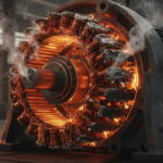
What happens to the grid when a transformer fails or runs poorly
Trouble spreads fast. A failing transformer can overheat, trip breakers, distort voltage, and interrupt service. It can also push stress onto nearby lines, switchgear, and backup equipment.
Sometimes the signs come first, humming changes, hot spots, oil leaks, or relay alarms. Other times, failure is sudden and expensive.
Common problems, maintenance basics, and safe work practices
Crews watch for overheating, insulation breakdown, winding faults, cracked bushings, loose connections, oil leaks, and cooling problems. A bad smell, odd sound, rising temperature, or repeated relay trip can all point to a deeper fault.
Simple maintenance goes a long way. Teams inspect oil condition, check for leaks, clean bushings, tighten connections, test insulation, and track hot spots with thermal tools. As of March 2026, many U.S. utilities are adding smart sensors and digital condition monitoring, partly because large replacement transformers can take more than two years to arrive. When lead times are that long, early warning matters.
Safety rules stay non-negotiable. Crews use lockout-tagout, grounding, barriers, insulated tools, and arc-flash PPE. Oil-filled units also bring fire risk, so spacing, fire protection, and trained access matter.
High-voltage equipment doesn’t forgive rushed work.
Conclusion
A voltage transformer in substation systems makes long-distance power delivery possible, efficient, and safer. It changes voltage, fits the transformer into the wider yard, supports protection and metering, and helps the grid stay steady under load. Learn the path, the parts, and the failure signs, and the whole substation starts to make a lot more sense.