Loose or aging medium-voltage (MV) connections don’t usually fail all at once. First, they heat up. That heat can stay hidden inside a compartment until insulation discolors, a lug anneals, or a joint starts to arc.
The TH110 thermal sensor targets that problem by measuring temperature right on the connection point. It’s wireless, self-powered from the conductor current, and built for harsh electrical spaces (IP65, about -25°C to 115°C). In practical terms, it lets you watch the real hot spots on switchgear cable lugs, transformer terminations, and busbar-to-cable links without running control wiring.
This guide explains how to install the thermal sensor th110 in MV cable terminations and joints: where to mount it, what to check first, and how to commission alarms so the data turns into action.
What you need to check before installing a TH110 on an MV cable
A TH110 install goes fast when the planning is done. Start by confirming the measured point, the load profile, and how you’ll receive the wireless signal. Also, check physical clearance, because MV compartments punish sloppy placement.
In the field, a good pre-check looks like this: confirm you have a stable metal surface to touch, verify expected current on that feeder, verify the gateway can hear Zigbee 2.4 GHz from the cabinet location, then plan a mount that won’t interfere with shutters, racking, or doors. Finally, confirm the sensor can sit where it won’t rub, rotate, or get pinched.
For manufacturer details on parts, ribbon handling, and tightening limits, keep the official documentation handy, for example the TH110 Installation Guide.
Pick the right measuring spot on the cable termination
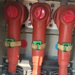
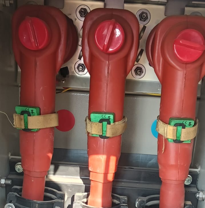
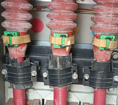
The sensor must touch the part that gets hot. On MV cable terminations, that usually means the lug barrel, the lug palm, the bolted interface, or the connector body. Those areas heat first because contact resistance rises when torque relaxes, surfaces oxidize, or strands creep under pressure.
Avoid mounting on the insulated cable jacket or stress control. Those surfaces track ambient more than joint temperature, so alarms come late. Also, avoid painted metal, grease films, or any spot with loose oxide scale. If you can’t get clean metal contact, you can’t trust the trend.
Placement also needs mechanical common sense. Don’t put the TH110 where it can rub a phase barrier, touch a moving shutter, or get dragged by a racked breaker. You want stable pressure and repeatable contact, because small shifts can change readings and hide a true hot spot.
Confirm the sensor can harvest enough energy and communicate
TH110 sensors harvest energy from the electromagnetic field around a current-carrying conductor. In plain terms, no load means no power, so you need enough current and enough “wrap length” at the active part to keep the device awake. A common rule used for planning is about 0.4 A per centimeter of contact perimeter on the energized part.
Before you install, check the expected operating current. If the feeder runs lightly loaded for long periods, plan for dropouts or delayed reporting. Also, plan where the sensor will sit so it has a solid contact area, not a narrow edge.
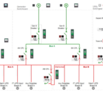
Wireless matters just as much. Zigbee at 2.4 GHz does not like steel compartments. A gateway outside the lineup might work, but distance and metal layers reduce reliability fast. If you can, plan the gateway location so the path crosses fewer steel barriers, and keep naming consistent so “Phase B, Feeder 3” is never confused later.
If the sensor mounts perfectly but the feeder rarely carries load, you’ll see gaps in data. That’s a power source issue, not a bad temperature joint.
How to install the thermal sensor TH110 in MV cable connections, step by step
Only qualified MV personnel should perform this work. Many sites require the compartment de-energized even if a device is rated for high-voltage environments (TH110 is designed for installation near active parts up to 52 kV in the right application). Follow your facility rules first.
A practical install flow looks like this:
- Apply site lockout/tagout (LOTO) and get the approved switching order.
- Open the compartment, then inspect the target joint for heat discoloration or looseness.
- Clean the contact surface to bare, dry metal where the sensor will touch.
- Size the ferromagnetic mounting ribbon to the perimeter, with extra length for the tie path (many teams add about 100 mm so the tie seats cleanly).
- Feed the ribbon through the sensor as instructed, without pressing on the thermistor pad.
- Place the TH110 on the lug or connector body, centered over the heat path.
- Wrap and tension the ribbon so it can’t slip under vibration.
- Lock the quarter-turn mechanism, then secure any supplied tape or retention wrap.
- Confirm clearance: doors close, shutters operate, and nothing pinches the ribbon.
- Re-energize per procedure, then verify the first stable readings.
Make the work area safe first (MV lockout, test, and arc-flash limits)
MV work starts with controlled energy. Follow the site LOTO, then test for the absence of voltage with an approved meter and method. Apply grounds where your rules require them. In addition, respect arc-flash boundaries and the PPE category defined by the facility arc-flash study.
Keep tools and hands out of arc zones. Also, avoid leaning into compartments. A dropped fastener can turn into a fault path in seconds, so slow down when you’re close to energized parts or stored-energy mechanisms.
Mount the TH110 so it stays tight and reads the real joint temperature
Accuracy comes from contact quality. Wipe the metal with a clean, dry cloth, then place the sensor so the thermistor pad sits flat on the lug or connector body. If the surface is curved, pick the flattest area that still represents the joint temperature rise.
Next, wrap the mounting ribbon and tension it with the recommended tool so it won’t creep. Many installs use a low tension setting (often “level 1” on common tie tools, with a maximum around 200 N) to avoid damaging hardware while still preventing slip. Trim excess ribbon cleanly so it can’t snag during maintenance.
After that, check orientation. The sensor must not rotate off the hot spot over time. Also confirm it doesn’t block breaker racking, shutter travel, or door clearances.
Commissioning, alarm settings, and troubleshooting after the install
Mounting is only half the job. Commissioning turns a sensor into a maintenance signal. Right after energization, focus on three things: the sensor joins the gateway, data updates on schedule (often around every 5 minutes in monitoring platforms), and alarms match how your equipment actually runs.
Pair the sensor to the gateway and confirm that data is updating
Put the gateway in discovery mode per your site process, then power the sensor by loading the circuit. Watch for the first reported temperature values. If your interface shows signal strength, use it. If not, confirm updates arrive consistently for at least a few cycles.
Labeling matters more than people expect. Map each sensor to the correct feeder, phase, and cabinet so alerts send a technician to the right door. For a pairing walkthrough that matches common field setups, see this pairing Schneider TH110 thermal sensor guide.
Set practical temperature alarms and respond to a hot-spot alert
Set two levels: a warning and a high alarm. Use your site standards first, then adjust based on connector ratings and normal ambient. A fixed number can work, but trends are usually better. A joint that rises faster than the other phases under similar load deserves attention even if it hasn’t crossed a hard limit.
When an alert hits, respond in a controlled order. Inspect torque and hardware condition, then look for corrosion, discoloration, strand damage, or insulation heat marks. After repairs, re-check temperatures under load and confirm the trend returns to normal.
A single hot reading can be noise. A rising trend on one phase is a problem developing in real time.
Fix the most common issues: bad contact, low load, or weak wireless signal
Most post-install problems trace to three causes:
- Bad thermal contact: Re-seat the sensor on bare metal, then re-tension the ribbon so it can’t move.
- Load current too low: Confirm the feeder actually carries enough current to self-power the sensor, then move the sensor to a point with better coupling if needed.
- Weak Zigbee path: Reduce metal barriers where possible, or reposition the gateway closer to the lineup.
If you want a real-world reference for what “good” looks like after commissioning, this TH110 cable temperature monitoring case study shows how trending and alarms caught a rising feeder temperature before damage spread.
Conclusion
Installing a TH110 on MV cable connections works when you treat it like a measurement instrument, not a sticker. Choose the joint that actually heats, ensure solid metal contact and enough current for self-power, then mount it so it can’t slip. After that, verify updates, set meaningful alarms, and watch trends across phases. Above all, follow MV safety rules every time, because no temperature reading is worth a risky compartment entry.